Charging barrel of infrared dehumidification, crystallization and drying all-in-one machine and crystallization and drying all-in-one machine

An infrared, all-in-one technology, applied in plastic recycling and other directions, can solve the problems of plastic particle adhesion, complex internal wiring safety hazards, adhesion and other problems, and achieve the effects of good heating, high viscosity and good turning effect.

Pending Publication Date: 2021-04-09
ZHANGJIAGANG LIANDA MACHINERY
View PDF1 Cites 4 Cited by
  • Summary
  • Abstract
  • Description
  • Claims
  • Application Information

AI Technical Summary

Problems solved by technology

[0005] 2. The rotation of the filter cartridge of the current plastic particle dryer is driven by the motor, and the filter cartridge is generally axially slid and can be pulled out from the inside of the casing, which is convenient for cleaning and maintenance. Therefore, the installation of the motor needs to be done with The filter cartridge is slid out from the inside of the casing together, and the other end of the entire plastic particle dryer needs to be installed with other electrical components such as a fan, which leads to wiring at both ends of the equipment, complicated internal wiring and potential safety hazards
[0006] 3. When the infrared light box of the current plastic particle dryer is heated, although the light tube is facing the direction of the material, the heat generated by the light tube will also be transferred to the light box, so that the plastic particles will be heated when they fall on the light box. And it adheres to the light box, which leads to serious adhesion of plastic particles on the light box

Method used


Image

  • Charging barrel of infrared dehumidification, crystallization and drying all-in-one machine and crystallization and drying all-in-one machine
  • Charging barrel of infrared dehumidification, crystallization and drying all-in-one machine and crystallization and drying all-in-one machine
  • Charging barrel of infrared dehumidification, crystallization and drying all-in-one machine and crystallization and drying all-in-one machine

Examples


Embodiment 1

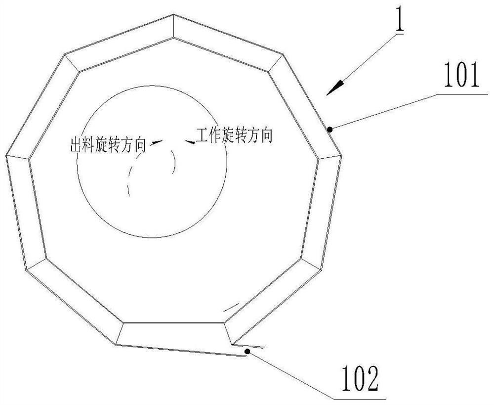
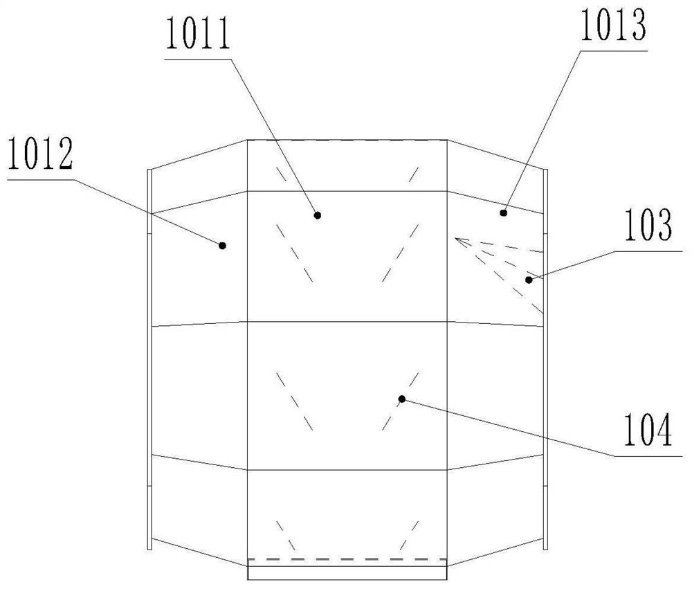
[0051] Such as Figure 1 to Figure 2 As shown, a barrel 1 of an infrared dehumidification, crystallization and drying integrated machine, the cross-sectional shape of the barrel 1 is a polygon with sides larger than a pentagon, preferably, the polygon is a pentagon to a decagon A suitable polygon is selected according to the size of the barrel 1. One end of the barrel 1 is open and is the feeding end. Each plate surface 101 constituting the polygon shaped barrel 1 includes a middle plate portion 1011 and a set The first closing plate portion 1012 and the second closing plate portion 1013 at both ends of the middle plate portion 1011, the first closing plate portion 1012 and the second closing plate portion 1013 form an obtuse angle with the middle plate portion 1011 and close towards the middle , the side wall of the barrel 1 is provided with a discharge port 102 . In this embodiment, the discharge port 102 of the barrel 1 is arranged at the junction of two adjacent plate sur...

Embodiment 2

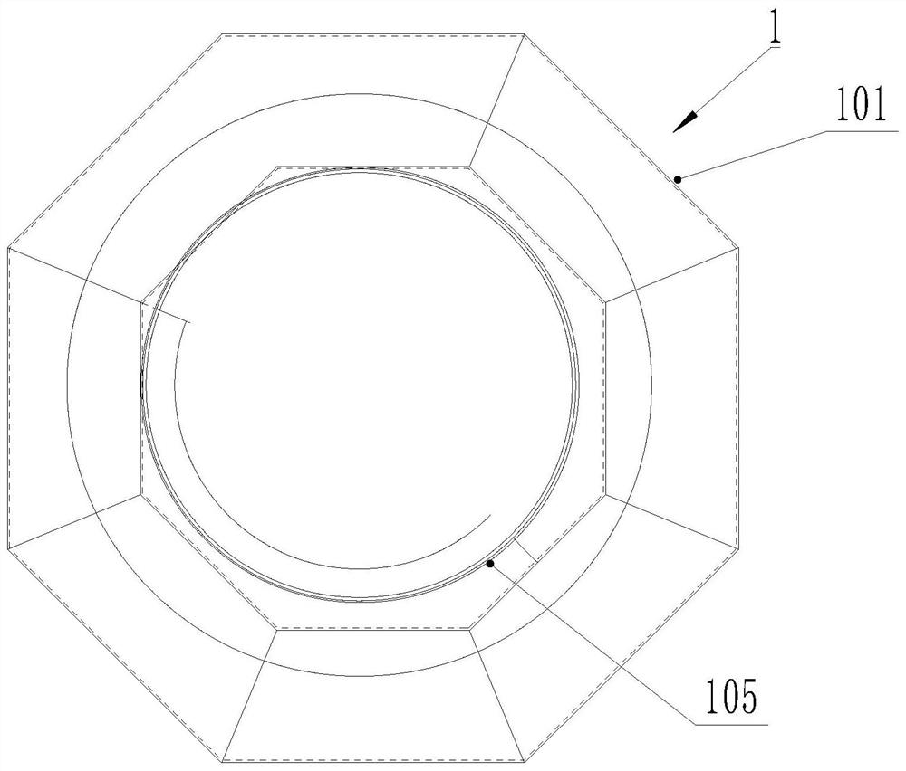
[0055] Such as image 3 with Figure 4As shown, this embodiment discloses another barrel 1 of an infrared dehumidification, crystallization and drying integrated machine. The structure of the barrel 1 is similar to that of Example 1, except that in this embodiment, the side wall of the barrel 1 is not provided with an opening. , and the opening at the other end of the barrel 1 is set as a discharge port; at this time, a spiral discharge guide plate 105 is provided inside the barrel 1 to facilitate material discharge. However, in this embodiment, in order to increase the speed of discharging, and at the same time enable the material to be discharged more thoroughly and avoid residues, in this embodiment, the turning structure includes several groups of turning plates 104 arranged in parallel. The plate surface of the plate 104 intersects with the center line of the barrel to form an angle, and each group of turning plates is arranged on the middle plate portion 1011, and prefe...

Embodiment 3

[0057] Such as Figure 5 to Figure 10 As described above, an infrared dehumidification, crystallization and drying integrated machine includes a frame 2, an organic casing 3 is fixed on the frame 2, and the barrel 1 is mounted on the frame 2 to rotate around the central axis. The frame 2 includes a fixed support frame 21 and a slide seat 22 axially slidably mounted on the fixed support frame 21. Two pairs of support rollers 11 are installed on the slide seat 22, and a convenient barrel 1 is installed on the outer periphery of the barrel 1. Rotating rotary support structure 13 , the barrel 1 is rotatably mounted on the support roller 11 through the rotary support structure 13 , and the limiting device 10 is installed on the sliding seat 22 to limit the axial position of the barrel 1 . One of the two pairs of support rollers 11 is an active support roller 12, the motor 8 is fixed on the frame, and the output shaft of the motor 8 is connected to the axle of the active support rol...


PUM


Abstract

The invention discloses a charging barrel of an infrared dehumidification, crystallization and drying all-in-one machine and a drying machine. The cross section of the charging barrel is in the shape of a polygon with the side number larger than the side number of a pentagon; one end of the charging barrel is open and serves as a feeding end; each plate face forming the polygonal charging barrel comprises a middle plate part, a first closing-in plate part and a second closing-in plate part; the first closing-in plate part and the second closing-in plate part are arranged at the two ends of each middle plate part, form obtuse angles with each middle plate part and are closed in the middle; a discharge hole is formed in the side wall of the charging barrel or an opening in the other end of the charging barrel is set as the discharge hole; and when the opening in the other end of the charging barrel is set as the discharge hole, a spiral discharging guide plate facilitating discharging of materials is arranged in the charging barrel. According to the drying machine, the charging barrel is used, the better material turning effect can be achieved under the condition that no material turning plate exists, the machining difficulty is low, and the drying machine is suitable for crystallization and drying of plastic particles with high viscosity.

Description

technical field [0001] The invention relates to a material cylinder of an infrared dehumidification, crystallization and drying integrated machine, and also relates to an infrared dehumidification, crystallization and drying integrated machine using the material cylinder. Background technique [0002] In order to improve the quality of plastic products, their raw materials are generally processed into plastic particles. Loose plastic particles are susceptible to moisture when exposed to air. Therefore, loose plastic particles need to be dried before being processed into plastic products. The common method is to use a heat dissipation fan to directly send the heat of the heater through the pipeline into a pile of loose raw materials to dry the raw materials. The heat will diffuse in the loose raw materials, and the peripheral raw materials will be heated later, and the raw materials are in close contact with each other, which reduces the contact area between the heat and the...

Claims


Application Information

Patent Timeline
Patent Type & Authority Applications(China)
IPC IPC(8): B29B13/06
CPCB29B13/065B29B13/08F26B3/28F26B11/02F26B25/16F26B2200/08
Inventor 郑勇潘学明
Owner ZHANGJIAGANG LIANDA MACHINERY
Why Eureka
Try Eureka