
Impeller structure submersible pump assembly with floating balance function

A technology for submersible pumps and drive structures, applied to pump components, parts of pumping devices for elastic fluids, pumps, etc., which can solve problems such as deformation of the diversion shell, displacement of the impeller structure, and impact on service life, so as to avoid up and down Float, prevent relative displacement, improve the effect of working stability

Inactive Publication Date: 2021-04-09
温州兽班机械科技有限公司
View PDF0 Cites 0 Cited by
  • Summary
  • Abstract
  • Description
  • Claims
  • Application Information

AI Technical Summary

Problems solved by technology

[0003] Most of the impeller structures in the existing submersible pump components do not have the function of floating balance. The impeller structure is prone to relative displacement during operation, which affects its service life and the guide shell is also prone to deformation.

Method used


Image

  • Impeller structure submersible pump assembly with floating balance function
  • Impeller structure submersible pump assembly with floating balance function
  • Impeller structure submersible pump assembly with floating balance function

Examples


Embodiment Construction

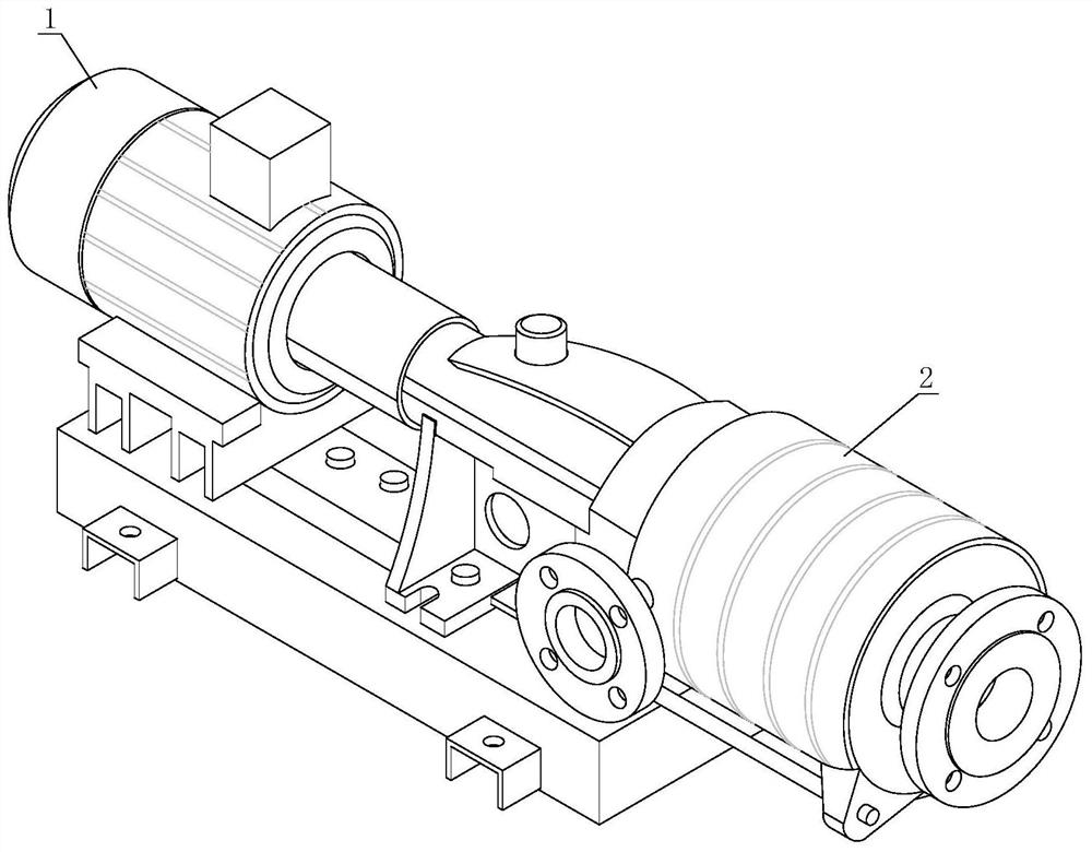
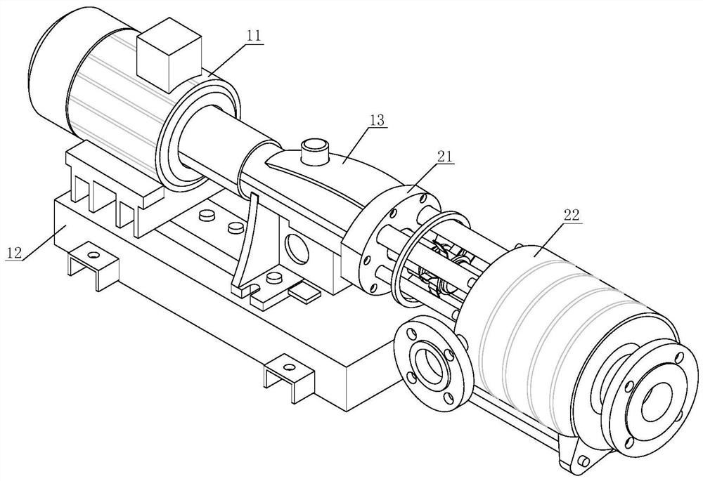
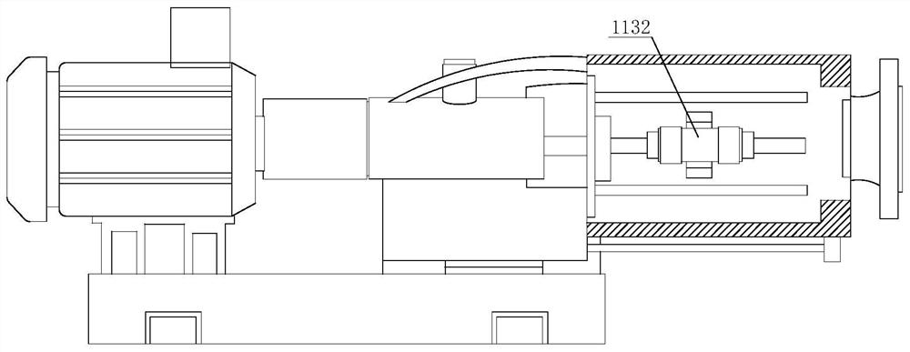
[0028] The following will clearly and completely describe the technical solutions in the embodiments of the present invention with reference to the accompanying drawings in the embodiments of the present invention. Obviously, the described embodiments are only some, not all, embodiments of the present invention. Based on the embodiments of the present invention, all other embodiments obtained by persons of ordinary skill in the art without making creative efforts belong to the protection scope of the present invention.

[0029] refer to figure 1 , figure 2 and Figure 5 , an impeller structure submersible pump assembly with floating balance, including a load-bearing drive mechanism 1 and an auxiliary submersible pump mechanism 2, one end of the load-bearing drive mechanism 1 is connected to the auxiliary submersible pump mechanism 2, and the load-bearing drive mechanism 1 includes a drive structure 11, a load-bearing structure 12 and The arc-shaped pressing plate 13, the lo...


PUM


Abstract

The invention discloses an impeller structure submersible pump assembly with the floating balance function. The impeller structure submersible pump assembly comprises a bearing driving mechanism and an auxiliary submersible pump mechanism, and one end of the bearing driving mechanism is connected with the auxiliary submersible pump mechanism. According to the submersible pump assembly, four magnetic rods are further installed on the outer side of a disc body, magnetic rings are fixedly arranged at the positions, close to the edges, of the two ends of the outer side of a positioning sleeve, the magnetism of the magnetic rings is the same as that of the magnetic rods, so that when a driving rotating rod is utilized to drive an impeller structure to rotate at a high speed, the position of the impeller structure can be limited through the magnetic rods arranged on the periphery of the impeller structure, meanwhile, the magnetic rings and the magnetic rods are the same in magnetism, the distances between the magnetic rods and the magnetic rings are equal, according to the principle that like poles repel each other, certain counter-acting force can be generated between the magnetic rods and the magnetic rings, the impeller structure is limited in the centers of the magnetic rods, and therefore, the purpose of balancing the impeller structure is achieved, the impeller structure is prevented from floating up and down during working, and good performance of the impeller structure is prevented from being damaged.

Description

technical field [0001] The invention relates to the technical field of submersible pumps, in particular to an impeller structure submersible pump assembly with floating balance. Background technique [0002] Submersible pump is an important equipment for deep well water extraction. When in use, the whole unit submerges into the water to extract groundwater to the surface. It can be used for domestic water, mine emergency, industrial cooling, farmland irrigation, seawater lifting, ship load adjustment, and fountain landscape. , with the advancement of science and technology, people have put forward higher requirements for the use of submersible pumps, and the swirl pump is a kind of equipment named because of the rotating vortex motion of the internal fluid. Swirl pumps are mostly used to pump complex media or fluids containing impurities, such as two-phase fluids containing garbage, short fiber materials or feces. Swirl pumps are also called non-clogging pumps, and swirl sta...

Claims


Application Information

Patent Timeline
Patent Type & Authority Applications(China)
IPC IPC(8): F04D13/08F04D29/66F04D29/22F04D29/20F04D29/42F04D29/62F04D29/08
CPCF04D13/08F04D29/086F04D29/20F04D29/2222F04D29/426F04D29/4293F04D29/628F04D29/669
Inventor 石贞
Owner 温州兽班机械科技有限公司
Learn More