
High precision sample rotating stage device based on atomic force microscope

A technology of atomic force microscope and rotary table, which is applied in the field of nanoscience and nanotechnology, can solve the problems of quantitative mechanical test result errors, different force states, and difficult calibration of normal coefficients and lateral coefficients, and achieve the elimination of normal bending and lateral bending. Effects of Torsional Coupling, Increased Efficiency, Broadened Range of Use and Range of Research

Active Publication Date: 2022-03-01
DONGHUA UNIV
View PDF6 Cites 1 Cited by
  • Summary
  • Abstract
  • Description
  • Claims
  • Application Information

AI Technical Summary

Problems solved by technology

[0004] At present, the stage that comes with the commercial atomic force microscope can hardly complete the rotation of the precise angle. To achieve the precise angle rotation, the user usually develops the relevant rotation device, and most of the existing rotation devices are manual rotation devices.
When using an atomic force microscope to test different crystal orientations of crystal materials, the sample stage can only be scanned along different crystal orientations through piezoelectric ceramics. However, when it comes to the study of mechanical properties, due to the relative movement direction Different positions lead to different stress states of the needle tip and the micro-cantilever, which couples the normal bending and lateral torsion of the micro-cantilever, making it more difficult to calibrate the normal and lateral coefficients. Larger errors, especially when performing lateral force experiments, the direction of motion can only be perpendicular to the direction of the cantilever, so the test of different crystal orientations can only be achieved by rotating the sample

Method used


Image

  • High precision sample rotating stage device based on atomic force microscope
  • High precision sample rotating stage device based on atomic force microscope
  • High precision sample rotating stage device based on atomic force microscope

Examples


Embodiment Construction

[0037] The present invention will be further described below in combination with specific embodiments. It should be understood that these examples are only used to illustrate the present invention and are not intended to limit the scope of the present invention. In addition, it should be understood that after reading the teachings of the present invention, those skilled in the art can make various changes or modifications to the present invention, and these equivalent forms also fall within the scope defined by the appended claims of the present application.

[0038] In the description of the present invention, it should be understood that the orientation or positional relationship indicated by the terms "center", "inner", "outer", "upper", "lower" etc. is based on the orientation or positional relationship shown in the drawings , is only for the convenience of describing the present invention and simplifying the description, but does not indicate or imply that the referred de...


PUM


Abstract

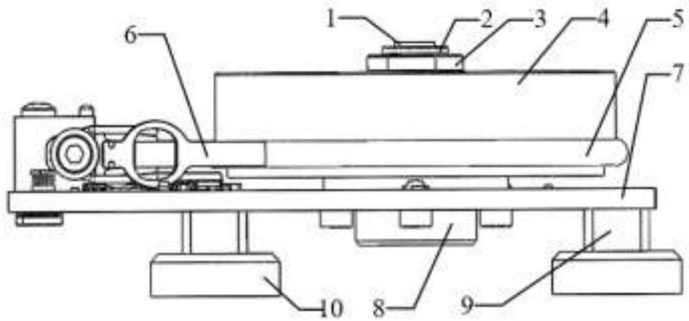
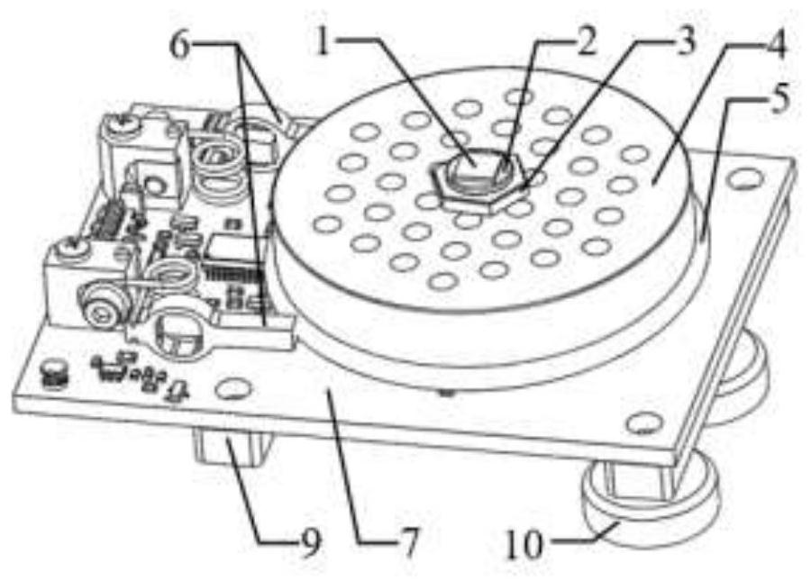
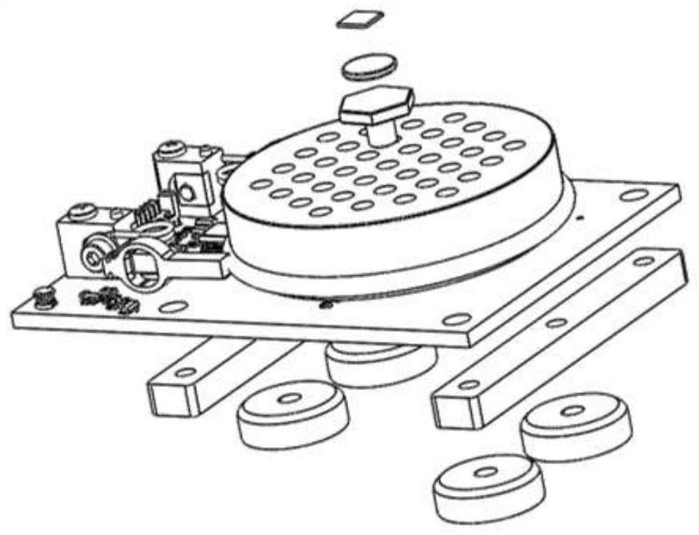
The invention relates to a high-precision sample turntable device based on an atomic force microscope, which includes a turntable main body, a sample mounting seat on the turntable main body, and a magnetic base for fixing the turntable main body; the turntable main body passes through the The magnetic base is fixed on the platform of the atomic force microscope scanner; the main body of the rotating stage includes a sample stage, a magnetic rotary encoder and two elliptical piezoelectric resonant motors. A plastic ring is fixed on the side of the sample stage, and the top of the elliptical piezoelectric resonant motor is connected to The plastic ring is in close contact, and two elliptical piezoelectric resonant motors are installed opposite to each other, one is used to push the plastic ring to move, and the other is used to pull the plastic ring to move in the opposite direction; the disk of the magnetic rotary encoder is installed on the sample stage. The device of the invention is suitable for providing high-precision angle rotation for samples under the condition of limited size space and limited weight of the atomic force microscope, which broadens the application occasion and research scope of the atomic force microscope.

Description

technical field [0001] The invention belongs to the field of nano science and technology, and relates to a high-precision sample rotary table device based on an atomic force microscope, in particular to a high-precision sample rotary table device based on an atomic force microscope suitable for quantitative mechanical testing and analysis of crystal anisotropy. Background technique [0002] The working principle of the atomic force microscope is to fix the probe on the free end of the micro-cantilever. When the probe scans the sample surface, the interaction force between the atoms generated between the needle tip and the sample surface will cause the micro-cantilever to slightly deform (bending and Torsion), as a measure of the force between the needle tip and the sample, the back of the cantilever is used to reflect the laser light to the photodetector to measure the tiny deformation of the micro-cantilever, and the surface morphology and corresponding mechanical properties...

Claims


Application Information

Patent Timeline
Patent Type & Authority Patents(China)
IPC IPC(8): G01Q60/24G01Q60/38
CPCG01Q60/24G01Q60/38
Inventor 彭倚天虞康郎浩杰
Owner DONGHUA UNIV
Learn More