Correction method of LED display screen and related device

A technology of LED display screen and calibration method, which is applied to static indicators, instruments, etc., can solve the problem that thermal compensation calibration cannot achieve the expected effect, and achieve the effect of improving calibration efficiency

Inactive Publication Date: 2021-04-09
SHENZHEN ABSEN OPTOELECTRONIC CO LTD
0 Cites 5 Cited by

AI-Extracted Technical Summary

Problems solved by technology

[0004] The embodiment of the present application discloses a calibration method and a related device for an LED display screen. The thermal compensation correction coefficient and the point-by-point correction coefficient are stored separately, and the point-by-point thermal compensation correction coefficient is calculated according to the thermal compensation correction coefficient and the point-by-point correction coefficient. Finally, a one-...

Method used

As the calibration equipment of LED display cabinets such as LED control computers, the brightness and chromaticity data of the LED display cabinets can be collected by external devices such as cameras, and calculated point-by-point correction coefficient matrix according to the bright and chromaticity data, the point-by-point The correction coefficient matrix includes point-by-point correction coefficients, and the point-by-point correction coefficients are correlated with the module positions of the LED display cabinet. Optionally, the LED controller connected to the network of the calibration equipment of the LED display cabinet such as the LED control computer can perform point-by-point calibration on the LED display cabinet according to the calculated point-by-point correction coefficient of the LED display cabinet, and the LED display cabinet can be corrected point by point. Point correction is a technology used to improve the brightness uniformity and color fidelity of the LED display, that is, through the brightness (and chromaticity) data of each pixel (or each primary color sub-pixel) area on the LED display Collect, give the correction coefficient of each primary color sub-pixel or the correction coefficient matrix of each pixel, and feed it back to the control system of the display screen, and the control system applies the correction coefficient to realize the correction of each pixel (or each primary color sub-pixel Pixel) differential drive, so that the picture of the LED display is pure and delicate, and the color is truly restored.
In summary, by implementing the embodiment of the present application, the thermal compensation correction coefficient originally included in the point-by-point correction coefficient is separated, and the thermal compensation correction coefficient and the point-by-point correction coefficient are respectively stored, and according to the thermal compensation correction coefficient Calculate the point-by-point thermal compensation correction coefficient and perform one-time correction, which can solve the problem that the thermal compensation correction cannot achieve the expected effect caused by the change of the module position of the LED display box after thermal compensation correction, and The thermal compensation correction coefficients stored separately only need to be collected once for LED display cabinets with the same structure and PCB layout, which greatly improves the correction efficiency.
In the LED display correction device 60 described in Fig. 6, the thermal compensation correction coefficient originally included in the point-by-point correction coefficient is separated, and the thermal compensation correction coefficient and the point-by-point correction coefficient are respectively stored, and are corrected according to the thermal compensation Coefficients and point-by-point correction coefficients are calculated to obtain point-by-point thermal compensation correction coefficients, and then one-time correction can solve the problem that the thermal compensation correction cannot achieve the expected effect caused by the change of the module position of the LED display box after thermal compensation correction. Moreover, the thermal compensation correction coefficients stored separately only need to be collected once for LED display cabinets with the same structure and PCB layout, which greatly improves the correction efficiency.
In the LED display correction device described in Fig. 5, the thermal compensation correction coefficient originally included in the point-by-point correction coefficient is separated, and the thermal compensation correction coefficient and the point-by-point correction coefficient are stored respectively, and according to the thermal compensation correction coefficient Coefficients and point-by-point correction coefficients are calculated to obtain point-by-point thermal compensation correction coefficients, and then one-time correction can solve the problem that the thermal compensation correction cannot achieve the expected effect caused by the change of the module position of the LED display box after thermal compensation correction. Moreover, the thermal compensation correction coefficients stored separately only need to be collected once for LED display cabinets with the same structure and PCB layout, which greatly improves the correction efficiency.
In the embodiment of the present application, because the thermal compensation correction coefficient used in the original correction method is included in the point-by-point correction coefficient, and the point-by-point correction coefficient has correlation with the module position of the LED display box, so The thermal compensation correction coefficient is also related to the position of the module of the LED display cabinet, that is, when the position of the module of the LED display cabinet changes, the thermal compensation correction coefficient will be affected by the change of the position of the module so that the thermal Compensation and correction can not achieve the expected effect. In the embodiment of this application, the thermal compensation correction coefficient originally included in the point-by-point correction coefficient is separated, and the thermal compensation correction coefficient and the point-by-point correction coefficient are stored separately. According to the thermal compensation correction coefficient and the point-by-point correction The coefficient is calculated to obtain the point-by-point thermal compensation correction coefficient, and then one-time correction is performed, thus solving the problem that the thermal compensation correction cannot achieve the expected effect caused by the change of the module position of the LED display box after thermal compensation correction, and after separate storage The thermal compensation correction coefficient only needs to be collected once for the LED display cabinet with the same structure and PCB layout, which greatly improves the correction efficiency.
In the embodiment of the present application, because the thermal compensation correction coefficient used in the original correction method is included in the point-by-point correction coefficient, and the point-by-point corr...

Abstract

The embodiment of the invention provides a correction method of an LED display screen and a related device. The method comprises the following steps: calculating to obtain a point-by-point thermal compensation correction coefficient according to the thermal compensation correction coefficient and the point-by-point correction coefficient of an LED display screen box body; and correcting the LED display screen box body according to the point-by-point thermal compensation correction coefficient. According to the method and the device provided by the invention, the thermal compensation correction coefficient and the point-by-point correction coefficient are separately stored, and one-time correction is carried out after the point-by-point thermal compensation correction coefficient is calculated according to the thermal compensation correction coefficient and the point-by-point correction coefficient; the invention solves the problem that due to the fact that the position of the LED display screen module is changed, thermal compensation correction cannot achieve the expected effect; besides, the separated thermal compensation correction coefficient only needs to be collected once for an LED display screen box of the same structure and PCB layout, and the correction efficiency is greatly improved.

Application Domain

Static indicating devices

Technology Topic

PhysicsEngineering +2

Image

  • Correction method of LED display screen and related device
  • Correction method of LED display screen and related device
  • Correction method of LED display screen and related device

Examples

  • Experimental program(1)

Example Embodiment

[0080] In order to make the objectives, technical solutions and advantages of the present application clearer, the present application will be further described below with reference to the accompanying drawings.
[0081] The terms "first" and "second" in the description, claims and drawings of the present application are only used to distinguish different objects, rather than to describe a specific order. Furthermore, the terms "comprising" and "having", and any variations thereof, are intended to cover non-exclusive inclusion. For example, a process, method, system, product or device, etc. that includes a series of steps or units is not limited to the listed steps or units, but optionally also includes unlisted steps or units, etc., or optional It also includes other steps or units inherent to these processes, methods, products or devices, etc.
[0082] Reference herein to an "embodiment" means that a particular feature, structure, or characteristic described in connection with the embodiment can be included in at least one embodiment of the present application. The appearances of the phrase in various places in the specification are not necessarily all referring to the same embodiment, nor a separate or alternative embodiment that is mutually exclusive of other embodiments. Those skilled in the art will understand, both explicitly and implicitly, that the embodiments described herein may be combined with other embodiments.
[0083] In this application, "at least one (item)" means one or more, "plurality" means two or more, "at least two (item)" means two or three and three In the above, "and/or" is used to describe the relationship of related objects, indicating that there can be three kinds of relationships, for example, "A and/or B" can mean: only A exists, only B exists, and both A and B exist three A case where A and B can be singular or plural. The character "/" generally indicates that the associated objects are an "or" relationship. "At least one of the following" or similar expressions, refers to any combination of these items. For example, at least one (a) of a, b or c, can mean: a, b, c, "a and b", "a and c", "b and c", or "a and b and c" ".
[0084] The embodiments of the present application provide a method for calibrating an LED display screen. In order to describe the solution of the present application more clearly, the following first introduces some knowledge related to the calibration of the LED display screen.
[0085] LED display box: The LED display box is simply a screen composed of several display units (unit display panels or LED display modules) that can be combined and spliced. In order to meet different environments, plus a set of appropriate controllers (main control board or control system), various specifications of display boards (or unit boxes) can be combined with controllers of different control technologies to form many kinds of LED displays. screen to meet different display needs.
[0086] LED display module: LED display module is one of the main components that make up the finished LED display. It is mainly composed of LED lights, PCB circuit boards, driver ICs, resistors, capacitors and plastic kits.
[0087] Point-by-point correction: Point-by-point correction is a technology used to improve the brightness uniformity and color fidelity of the LED display, that is, by adjusting the brightness ( and chromaticity) data are collected, the correction coefficient of each primary color sub-pixel or the correction coefficient matrix of each pixel is given, and it is fed back to the control system of the display screen, and the control system applies the correction coefficient to realize the correction of each pixel ( Or the differential drive of each primary color sub-pixel), so that the picture of the LED display is pure and delicate, and the color is truly restored.
[0088] The embodiments of the present application will be described below with reference to the accompanying drawings in the embodiments of the present application.
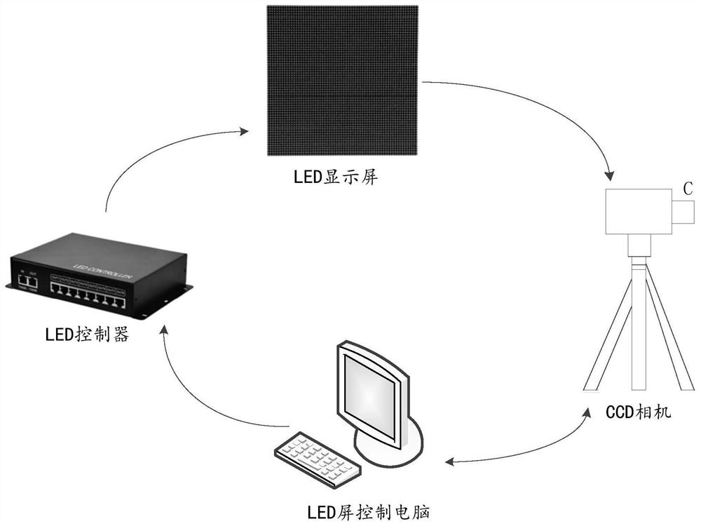
[0089] see figure 1 , figure 1 This is a schematic structural diagram of a cabinet calibration of an LED display screen provided by an embodiment of the present application. like figure 1 As shown, the architecture diagram includes the LED display box, the LED controller, the control computer and the camera. Among them, the camera is used to collect the brightness and chromaticity data of the LED box, and transmit the collected brightness and chromaticity data to the control computer. The control computer calculates and obtains the point-by-point correction coefficient. The LED controller uses the calculated point-by-point correction coefficient to perform point-by-point chromaticity correction on the LED display cabinet. The point-by-point chromaticity correction is based on the principle of RGB color matching, and solves the problem of chromaticity deviation by changing the color coordinates of the RGB three colors. When performing point-by-point chromaticity correction, the color coordinates of the corrected RGB three colors should be reasonably selected to avoid color distortion. Light-by-light chromaticity correction is to adjust the brightness and color uniformity of each LED light. The above calibration structure diagram is suitable for the calibration of factory standardization and standardized management. The cabinets can be freely spliced, the edges of the cabinets are automatically corrected, and the calibration angle is consistent and minimal, with high calibration efficiency and low calibration cost.
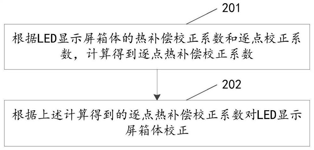
[0090] see figure 2 , figure 2 A schematic flowchart of a method for calibrating an LED display screen provided in an embodiment of the present application, the method includes but is not limited to the following steps:
[0091] Step 201: Calculate the point-by-point thermal compensation correction coefficient according to the thermal compensation correction coefficient and the point-by-point correction coefficient of the LED display cabinet.
[0092]According to the thermal compensation correction coefficient and point-by-point correction coefficient of the LED display box, the point-by-point thermal compensation correction coefficient is calculated; wherein, the thermal compensation correction coefficient is related to the mechanical structure of the LED display box and is related to the LED display box. The module position of the LED display is irrelevant, that is, when the mechanical structure of the LED display cabinet changes, the thermal compensation correction coefficient of the LED display cabinet will also change, and the thermal compensation correction coefficient of the LED display cabinet will not change. It changes with the change of the module position; the point-by-point correction coefficient is related to the module position of the LED display cabinet, that is, when the module position of the LED display cabinet changes, the The point correction coefficient will also change accordingly; the point-by-point thermal compensation correction coefficient is related to the mechanical structure of the LED display box and has nothing to do with the module position of the LED display box, that is, when the mechanical structure of the LED display box is When the change occurs, the point-by-point thermal compensation correction coefficient of the LED display cabinet will also change, but it will not change with the change of the module position of the LED display cabinet. From this, it can be seen that by using the point-by-point thermal compensation correction coefficient to correct the LED display cabinet in this embodiment, the point-by-point thermal compensation correction can still achieve the expected effect even when the module position of the LED display cabinet is changed. Because the embodiment of the present application separates the thermal compensation correction coefficient originally included in the point-by-point correction coefficient, stores the thermal compensation correction coefficient and the point-by-point correction coefficient respectively, and calculates the point-by-point thermal compensation coefficient according to the thermal compensation correction coefficient and the point-by-point correction coefficient After compensating the correction coefficients, a one-time correction is performed, and the thermal compensation correction coefficients stored separately only need to be collected once for the LED display cabinets with the same structure and PCB layout, which greatly improves the correction efficiency.
[0093] Specifically, there are multiple possibilities for obtaining the calculation method of the point-by-point thermal compensation correction coefficient, and this embodiment provides a possible implementation method. Multiply the thermal compensation correction coefficient of the LED display box and the point-by-point correction coefficient, and take the result of the product of the two as the point-by-point thermal compensation correction coefficient. Among them, the point-by-point correction coefficient can be obtained by collecting the brightness and chromaticity data of the LED display cabinet, and calculating the point-by-point correction coefficient matrix according to the collected brightness and chromaticity data. The point-by-point correction coefficient matrix includes a plurality of different point-by-point correction coefficients. Correction coefficient, point-by-point correction coefficient is related to the module position of the LED display cabinet. The thermal compensation correction factor can be obtained by:
[0094] First, the LED display box is subjected to light-by-light chromaticity cold screen correction. Specifically, the cold screen correction is to complete the light-by-light chromaticity correction within one minute after the above-mentioned LED display box is lit at room temperature. Here The room temperature refers to about 25 degrees Celsius; the LED display box after the cold screen correction is used as the sample box. Optionally, the above point-by-point correction coefficient can also collect the brightness and chromaticity data of the sample box at this time, and calculate the Point correction coefficient matrix; then display the LED sample box at 100% brightness, and age it in white for about 30 minutes, so that the LED sample box reaches a thermal equilibrium state, which means that the thermal distribution of the LED sample box does not change and the maximum temperature does not change. Change again, that is, the LED sample box has reached thermal equilibrium; then collect the red brightness value matrix of the sample box after cold screen correction and reach thermal equilibrium state, by dividing the maximum value of the collected red brightness value matrix by the red brightness The result obtained by the value matrix is ​​used as the thermal compensation correction coefficient matrix. The thermal compensation correction coefficient matrix includes a plurality of thermal compensation correction coefficients, and the thermal compensation correction coefficient is only related to the mechanical structure of the LED display box, not with the LED display box. The module position of the body changes. The above-obtained point-by-point correction coefficients and thermal compensation correction coefficients are respectively stored in different locations to achieve the effect of coefficient separation. Further, the control computer connected to the LED controller network sends the thermal compensation correction coefficient matrix to the receiving card of the LED controller through the host computer software of the LED controller, so that the thermal compensation correction coefficient matrix and the point-to-point correction coefficient matrix are point-to-point. The coefficients are multiplied to obtain multiple point-by-point thermal compensation correction coefficients, so that the point-by-point thermal compensation correction function can be realized through the point-by-point thermal compensation correction coefficients.
[0095] In addition, you can also place the camera directly in front of the LED display box, so that the camera lens is at the center of the display surface of the LED display box, and adjust the focal length and aperture of the camera lens so that the LED display box is located in the camera viewfinder. Central location. Then adjust the camera to make the image of each pixel in the camera clearly visible, and make the LED display box display red through the LED controller. The upper computer control software controls the camera to collect the cold screen red brightness distribution data of each pixel as the first red. Matrix of luminance values. Then display the LED display box at 100% brightness, and age it in white for about 30 minutes, so that the LED display box reaches a state of thermal equilibrium. The thermal equilibrium state means that the thermal distribution of the LED display box does not change and the maximum temperature If it does not change, it is considered that the LED display box has reached a state of thermal equilibrium; then the LED display box is made to display red through the LED controller, and the upper computer control software controls the camera to collect the red brightness of each pixel of the thermal screen within the specified time. Distribution data as a second matrix of red luminance values. Finally, the difference between the red brightness value in the first red brightness value matrix and the red brightness value in the second red brightness value matrix is ​​calculated, and the difference obtained above is divided by the maximum value of the above differences, to obtain the LED display. The thermal compensation correction coefficient matrix of the screen box, the thermal compensation correction coefficient matrix includes a plurality of thermal compensation correction coefficients, and the thermal compensation correction coefficient is only related to the mechanical structure of the LED display box, not with the LED display box. The position of the module changes, and the products of the same LED display cabinet only need to be collected once, which greatly reduces the time for each LED display cabinet to calibrate to reach the thermal equilibrium state. The operation is simple and the efficiency is higher. The above-obtained point-by-point correction coefficients and thermal compensation correction coefficients are respectively stored in different locations to achieve the effect of coefficient separation.
[0096] Step 202: Correct the LED display cabinet according to the point-by-point thermal compensation correction coefficient calculated above.
[0097] It can be seen from the above step 201 that the calculated point-by-point thermal compensation correction coefficient has nothing to do with the module position of the LED display cabinet, that is, it does not change with the change of the module position. Under the circumstance, the LED display cabinet can also be corrected according to the point-by-point thermal compensation correction coefficient calculated above, so as to realize the point-by-point thermal compensation correction function. And separate the thermal compensation correction coefficient originally included in the point-by-point correction coefficient, store the thermal compensation correction coefficient and the point-by-point correction coefficient respectively, and calculate the point-by-point thermal compensation correction coefficient according to the thermal compensation correction coefficient and the point-by-point correction coefficient. One-time calibration is performed, and the separately stored thermal compensation correction coefficients only need to be collected once for LED display cabinets with the same structure and PCB layout, which greatly improves the calibration efficiency.
[0098] Specifically, the LED display box calibration device can use different point-by-point thermal compensation correction coefficients to calibrate the LED display box according to the temperature of the LED display box. Because the thermal compensation correction coefficients of the LED display cabinet at different temperatures are different, the product results of different thermal compensation correction coefficients and point-by-point correction coefficients also correspond to multiple different point-by-point thermal compensation correction coefficients. Correlate the temperature monitoring of the LED display cabinet with the point-by-point thermal compensation correction coefficient, that is, set several temperature thresholds, such as the first threshold, the second threshold, etc., when the monitored LED display cabinet temperature is less than the first threshold. , use the first point-by-point thermal compensation correction coefficient to correct the LED display box; when the monitored temperature of the LED display box is greater than the second threshold, use the second point-by-point thermal compensation correction coefficient to correct the LED display box; when monitoring When the temperature to the LED display box is not less than the first threshold and not greater than the second threshold, the LED display box is corrected by using the third point-by-point thermal compensation correction coefficient. Among them, the first threshold and the second threshold are not fixed values, and can be set differently according to different application scenarios. For example, the first threshold can be set to 50°C, and the second threshold can be set to 70°C . Therefore, the temperature monitoring of the LED display cabinet can be associated with the command under the point-by-point thermal compensation correction coefficient through the above correction method, so as to realize the automatic point-by-point thermal compensation correction function of the LED display cabinet.
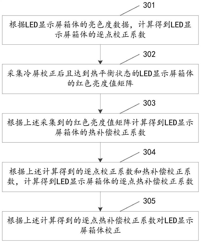
[0099] see image 3 , image 3 A schematic flowchart of another method for calibrating an LED display screen provided in the embodiment of the present application, the method includes but is not limited to the following steps:
[0100] Step 301: Calculate the point-by-point correction coefficient of the LED display screen cabinet according to the brightness and chromaticity data of the LED display screen cabinet.
[0101] Such as LED control computer and other LED display cabinet calibration equipment, the brightness and chromaticity data of the LED display cabinet can be collected through external devices such as cameras, and the point-by-point correction coefficient matrix can be calculated according to the brightness and chromaticity data. The point-by-point correction coefficient matrix Including a point-by-point correction coefficient, the point-by-point correction coefficient has a correlation with the module position of the LED display cabinet. Optionally, the LED controller connected to the calibration equipment of the LED display box such as the LED control computer can perform point-by-point correction of the LED display box according to the calculated point-by-point correction coefficient of the LED display box. Dot correction is a technology used to improve the brightness and color uniformity and color fidelity of LED display screens, that is, by comparing the brightness (and chromaticity) data of each pixel (or each primary color sub-pixel) area on the LED display screen. Carry out acquisition, give the correction coefficient of each primary color sub-pixel or the correction coefficient matrix of each pixel, and feed it back to the control system of the display screen, and the control system applies the correction coefficient to realize the correction of each pixel (or each primary color sub-pixel). Pixels) differential drive, so that the picture of the LED display is pure and delicate, and the color is truly restored.
[0102] Step 302: Collect the red brightness value matrix of the LED display cabinet after the cold screen correction and reaching a thermal equilibrium state.
[0103] In this step, the cold screen correction is performed on the LED display box. Specifically, the cold screen correction is to complete the chromaticity correction of the above LED display box within one minute after lighting at room temperature. The room temperature here refers to It is about 25 degrees Celsius; the LED display box after the cold screen correction is used as the sample box. Optionally, the above point-by-point correction coefficient can also collect the brightness and chromaticity data of the sample box at this time, and calculate the point-by-point correction coefficient matrix. ; Then display the LED sample box at 100% brightness, and carry out the white light aging step for about 30 minutes, so that the LED sample box reaches a thermal equilibrium state, which means that the thermal distribution of the LED sample box does not change and the maximum temperature does not change. , that is, it is considered that the LED sample box has reached thermal equilibrium; then the red brightness value matrix of the sample box after cold screen correction and reaching thermal equilibrium state is collected, and the collected red brightness and chromaticity value matrix can be used to calculate the thermal compensation correction of the LED sample box. coefficient.
[0104] Step 303: Calculate and obtain the thermal compensation correction coefficient of the LED display screen box according to the red luminance value matrix collected above.
[0105] The red brightness value matrix of the LED display box can be collected and obtained by the above step 302, and the red brightness and chromaticity value matrix can be used to calculate and obtain the thermal compensation correction coefficient of the LED sample box. Specifically, a result obtained by dividing the maximum value in the collected red luminance value matrix by the red luminance value matrix can be used as a thermal compensation correction coefficient matrix, and the thermal compensation correction coefficient matrix includes a plurality of thermal compensation correction coefficients, and The thermal compensation correction coefficient obtained by the method is related to the mechanical structure of the LED display screen box and has nothing to do with the module position of the LED display screen box. It should be noted that the point-by-point correction coefficient and thermal compensation correction coefficient obtained above are stored in different locations. By storing the point-by-point correction coefficient and thermal compensation correction coefficient separately, the thermal compensation correction coefficient can be made independent of the module position The influence of the change makes the thermal compensation correction still valid, and the point-by-point thermal compensation correction coefficient is calculated according to the thermal compensation correction coefficient and the point-by-point correction coefficient, and the one-time correction is performed, which can solve the problem of the LED display box after the thermal compensation correction. The problem that the thermal compensation correction caused by the change of the group position cannot achieve the expected effect, which greatly improves the correction efficiency.
[0106] Step 304 : According to the point-by-point correction coefficient and the thermal compensation correction coefficient obtained by the above calculation, calculate the point-by-point thermal compensation correction coefficient of the LED display screen cabinet.
[0107]From the above steps 301 to 303, the point-by-point correction coefficient and the thermal compensation correction coefficient of the LED display cabinet can be calculated and stored, and the two are stored in different positions to achieve the effect of coefficient separation. Further, the control computer connected to the LED controller network sends the thermal compensation correction coefficient matrix to the receiving card of the LED controller through the host computer software of the LED controller, so that the thermal compensation correction coefficient matrix and the point-to-point correction coefficient matrix are point-to-point. By multiplying the coefficients, multiple point-by-point thermal compensation correction coefficients can be obtained, so that the point-by-point thermal compensation correction function can be realized through the point-by-point thermal compensation correction coefficients. The point-by-point thermal compensation correction coefficient calculated above has nothing to do with the module position of the LED display cabinet, that is, it does not change with the change of the module position. Therefore, when the module position of the LED display cabinet changes, you can also According to the point-by-point thermal compensation correction coefficient calculated above, the LED display cabinet is corrected to realize the point-by-point thermal compensation correction function. And the embodiment of the present application separates the thermal compensation correction coefficient originally included in the point-by-point correction coefficient, stores the thermal compensation correction coefficient and the point-by-point correction coefficient respectively, and calculates the point-by-point thermal compensation according to the thermal compensation correction coefficient and the point-by-point correction coefficient. After compensating the correction coefficients, one-time correction is performed, and the thermal compensation correction coefficients stored separately only need to be collected once for LED display cabinets with the same structure and PCB layout, which greatly improves the correction efficiency.
[0108] Step 305: Correct the LED display cabinet according to the point-by-point thermal compensation correction coefficient calculated above.
[0109] Consistent with step 202 above.
[0110] see Figure 4 , Figure 4 A schematic flowchart of another method for calibrating an LED display screen provided by the embodiment of the present application, the method includes but is not limited to the following steps:
[0111] Step 401 : According to the brightness and chromaticity data of the LED display screen cabinet, calculate the point-by-point correction coefficient of the LED display screen cabinet.
[0112] Consistent with step 301 above.
[0113] Step 402: Collect the first red brightness value matrix and the second red brightness value matrix of the LED display screen cabinet.
[0114] In this step, the camera is placed in front of the LED display box, so that the camera lens is at the center of the display surface of the LED display box, the focal length and aperture of the camera lens are adjusted, and the LED display box is located in the center of the camera viewfinder. . Then adjust the camera to make the image of each pixel in the camera clearly visible, and make the LED display box display red through the LED controller. The upper computer control software controls the camera to collect the cold screen red brightness distribution data of each pixel as the first red. Matrix of luminance values. Then display the LED display box at 100% brightness, and age it in white for about 30 minutes, so that the LED display box reaches a state of thermal equilibrium. The thermal equilibrium state means that the thermal distribution of the LED display box does not change and the maximum temperature If it does not change, it is considered that the LED display box has reached a state of thermal equilibrium; then the LED display box is made to display red through the LED controller, and the upper computer control software controls the camera to collect the red brightness of each pixel of the thermal screen within the specified time. Distribution data as a second matrix of red luminance values. The collected first red brightness value matrix and second red brightness value matrix can be used to calculate and obtain the thermal compensation correction coefficient of the LED sample box.
[0115] Step 403 : Calculate and obtain the thermal compensation correction coefficient of the LED display screen box according to the first red brightness value matrix and the second red brightness value matrix collected above.
[0116] The first red brightness value matrix and the second red brightness value matrix of the LED display box can be collected from the above step 402, and the first red brightness value matrix and the second red brightness value matrix can be used to calculate and obtain the thermal energy of the LED sample box. Compensation correction factor. Specifically, the difference between the red luminance value in the first red luminance value matrix and the red luminance value in the second red luminance value matrix may be calculated first, and then the difference obtained above is divided by the maximum value among the above differences. , get the thermal compensation correction coefficient matrix of the LED display box, the thermal compensation correction coefficient matrix includes multiple thermal compensation correction coefficients, and the thermal compensation correction coefficient is only related to the mechanical structure of the LED display box, not with the LED display The module position of the screen cabinet changes, and the products of the same LED display cabinet only need to be collected once, which greatly reduces the time for each LED display cabinet to calibrate to reach the thermal equilibrium state. The operation is simple and the efficiency is higher. high. The above-obtained point-by-point correction coefficients and thermal compensation correction coefficients are respectively stored in different locations to achieve the effect of coefficient separation.
[0117] Step 404 : According to the point-by-point correction coefficient and the thermal compensation correction coefficient obtained by the above calculation, calculate the point-by-point thermal compensation correction coefficient of the LED display screen cabinet.
[0118] Consistent with step 304 above.
[0119] Step 405: Correct the LED display cabinet according to the point-by-point thermal compensation correction coefficient calculated above.
[0120] Consistent with step 305 above.
[0121] The methods of the embodiments of the present application are described in detail above, and the apparatuses of the embodiments of the present application are provided below.
[0122] see Figure 5 , Figure 5 This is a schematic structural diagram of a device 50 for calibrating an LED display screen provided in an embodiment of the present application. The LED display screen correction device may include a calculation unit 501, a correction unit 502, an aging unit 503 and a collection unit 504, wherein the description of each unit is as follows:
[0123] The calculation unit 501 is used to calculate and obtain the point-by-point thermal compensation correction coefficient according to the thermal compensation correction coefficient and the point-by-point correction coefficient of the LED display screen box; wherein, the thermal compensation correction coefficient is related to the mechanical structure of the LED display screen box , The point-by-point correction coefficient is related to the module position of the LED display cabinet, and the point-by-point thermal compensation correction coefficient is related to the mechanical structure of the LED display cabinet;
[0124] The calibration unit 502 is used for calibrating the LED display cabinet according to the point-by-point thermal compensation correction coefficient.
[0125] In the embodiment of the present application, because the thermal compensation correction coefficient used in the original correction method is included in the point-by-point correction coefficient, and the point-by-point correction coefficient is related to the module position of the LED display cabinet, the thermal compensation correction The coefficient is also related to the module position of the LED display box, that is, when the module position of the LED display box changes, the thermal compensation correction coefficient will be affected by the change of the module position, making the thermal compensation correction impossible. To achieve the expected effect, the embodiment of the present application separates the thermal compensation correction coefficient originally included in the point-by-point correction coefficient, stores the thermal compensation correction coefficient and the point-by-point correction coefficient respectively, and calculates it according to the thermal compensation correction coefficient and the point-by-point correction coefficient. The point-by-point thermal compensation correction coefficient is corrected at one time, which solves the problem that the thermal compensation correction cannot achieve the expected effect caused by the change of the module position of the LED display cabinet after thermal compensation correction, and the thermal compensation after separate storage The correction coefficient only needs to be collected once for the LED display cabinet with the same structure and PCB layout, which greatly improves the correction efficiency.
[0126] In a possible implementation manner, the calculation unit 501 is specifically configured to multiply the thermal compensation correction coefficient and the point-by-point correction coefficient to obtain the point-by-point thermal compensation correction coefficient.
[0127] In the embodiment of this application, the thermal compensation correction coefficient and the point-by-point correction coefficient are stored separately, and then by calculating the product of the thermal compensation correction coefficient and the point-by-point correction coefficient, the obtained point-by-point thermal compensation correction coefficient is only the same as that of the LED display cabinet. The mechanical structure of the LED display screen is related and has nothing to do with the module position of the LED display box, so that the thermal compensation correction is still effective even when the module position of the LED display box is changed.
[0128] In another possible implementation manner, the calibration unit 502 is specifically configured to calibrate the LED display screen cabinet according to the point-by-point thermal compensation correction coefficient when the module position of the LED display screen cabinet is changed.
[0129] In the embodiment of the present application, because the calculated point-by-point thermal compensation correction coefficient is only related to the mechanical structure of the LED display cabinet, and has nothing to do with the module position of the LED display cabinet, even in the LED display The thermal compensation correction is still valid when the module position of the cabinet is changed.
[0130] In yet another possible implementation, the correction unit 502 is further configured to correct the LED display box by using the first point-by-point thermal compensation correction coefficient if the temperature of the LED display box is lower than the first threshold; If the temperature of the screen box is greater than the second threshold, use the second point-by-point thermal compensation correction coefficient to correct the LED display box; if the temperature of the LED display box is not less than the first threshold and not greater than the second threshold, use the third The point-by-point thermal compensation correction coefficient corrects the LED display cabinet; wherein, the first point-by-point thermal compensation correction coefficient, the second point-by-point thermal compensation correction coefficient and the third point-by-point thermal compensation correction coefficient are point-by-point thermal compensation correction coefficients with different values .
[0131] In the embodiment of the present application, different point-by-point thermal compensation correction coefficients are used to calibrate the LED display screen cabinet according to the temperature of the LED display screen cabinet. Because the thermal compensation correction coefficients of the LED display cabinet at different temperatures are different, the product results of different thermal compensation correction coefficients and point-by-point correction coefficients also correspond to multiple different point-by-point thermal compensation correction coefficients. Correlate the temperature monitoring of the LED display cabinet with the point-by-point thermal compensation correction coefficient, that is, set several temperature thresholds, such as the first threshold, the second threshold, etc., when the monitored LED display cabinet temperature is less than the first threshold. , use the first point-by-point thermal compensation correction coefficient to correct the LED display box; when the monitored temperature of the LED display box is greater than the second threshold, use the second point-by-point thermal compensation correction coefficient to correct the LED display box; when monitoring When the temperature to the LED display box is not less than the first threshold and not greater than the second threshold, the LED display box is corrected by using the third point-by-point thermal compensation correction coefficient. Therefore, the automatic point-by-point thermal compensation correction function of the LED display cabinet can be realized through the above correction method.
[0132] In yet another possible implementation, the calibration unit 502 is further configured to perform cold screen calibration on the LED display screen box to obtain a sample box, and the sample box is the LED display screen box after the cold screen correction;
[0133] The aging unit 503 is used to perform white light aging treatment on the sample box until the sample box reaches a thermal equilibrium state, and the thermal equilibrium state is that the thermal distribution and the maximum temperature of the sample box do not change;
[0134] a collection unit 504, configured to collect the red luminance value matrix of the sample box in a thermal equilibrium state;
[0135] The calculation unit 501 is further configured to calculate and obtain the thermal compensation correction coefficient matrix of the LED display screen box according to the red brightness value matrix, and the thermal compensation correction coefficient matrix includes the thermal compensation correction coefficient.
[0136] In the embodiment of the present application, a method for obtaining a thermal compensation correction coefficient is provided. The cold screen correction is performed on the LED display box, and then white light aging treatment is performed until the thermal distribution and the maximum temperature of the LED display box no longer change. , and then collect the red brightness value matrix of the LED display box, and calculate the thermal compensation correction coefficient according to the collected red brightness value matrix. The thermal compensation correction coefficient obtained by the method is related to the mechanical structure of the LED display screen box and has nothing to do with the module position of the LED display screen box.
[0137] In another possible implementation manner, the calculation unit 501 is further configured to divide the maximum value in the red luminance value matrix by the red luminance value matrix to obtain a thermal compensation correction coefficient matrix of the LED display cabinet.
[0138]In the embodiment of the present application, a method for calculating a thermal compensation correction coefficient matrix is ​​provided, and the maximum value in the red brightness value matrix of the collected sample box is divided by the red brightness value matrix to obtain a thermal compensation correction coefficient matrix. The correction coefficient matrix includes the thermal compensation correction coefficients of the LED display cabinet at different temperatures.
[0139] In yet another possible implementation manner, the collection unit 504 is further configured to collect the first red luminance value matrix and the second red luminance value matrix of the LED display cabinet, and the first red luminance value matrix includes the LED display cabinet The red brightness value in the cold screen state, the second red brightness value matrix contains the red brightness value of the LED display cabinet in the thermal equilibrium state, and the thermal equilibrium state is that the thermal distribution and the maximum temperature of the LED display cabinet do not change;
[0140] The calculation unit 501 is further configured to calculate and obtain a thermal compensation correction coefficient matrix of the LED display cabinet according to the first red brightness value matrix and the second red brightness value matrix, where the thermal compensation correction coefficient matrix includes thermal compensation correction coefficients.
[0141] In the embodiment of the present application, a camera can be placed in front of the LED display box so that the camera lens is at the center of the display surface of the LED display box, and the focal length and aperture of the camera lens can be adjusted so that the LED display box is located at the center of the display surface of the LED display box. The center position of the camera's viewfinder. Adjust the camera to make the image of each pixel in the camera clearly visible, and make the LED display box display red through the LED controller. The upper computer control software controls the camera to collect the cold screen red brightness distribution data of each pixel (that is, the first one above. red luminance value matrix). The LED display box is subjected to cold screen correction, and then white light aging treatment is performed to make it reach a thermal equilibrium state. The LED display box is made to display red through the LED controller, and the upper computer control software controls the camera to complete each acquisition within a specified time. The hot screen red luminance distribution data of each pixel (that is, the above-mentioned second red luminance value matrix). Then, according to the collected first red brightness value matrix and second red brightness value matrix, a thermal compensation correction coefficient matrix of the LED display cabinet can be calculated, and the thermal compensation correction coefficient matrix includes thermal compensation correction coefficients. The thermal compensation correction coefficient obtained by this method is related to the mechanical structure of the LED display cabinet and has nothing to do with the module position of the LED display cabinet, and only needs to be collected once for the products of the same LED display cabinet. It greatly reduces the time for each LED display cabinet to reach a thermal equilibrium state, with simple operation and higher efficiency.
[0142] In another possible implementation manner, the calculating unit 501 is further configured to divide the difference between the red luminance value in the first red luminance value matrix and the red luminance value in the second red luminance value matrix by the difference value of the difference. The maximum value, the thermal compensation correction coefficient matrix of the LED display cabinet is obtained.
[0143] In the embodiment of the present application, a method for calculating a thermal compensation correction coefficient matrix is ​​provided, the difference between the red luminance value in the first red luminance value matrix and the red luminance value in the second red luminance value matrix is ​​calculated, and the above obtained The difference of , respectively, is divided by the maximum value of the above differences to obtain the thermal compensation correction coefficient matrix of the LED display box, and the thermal compensation correction coefficient matrix includes the thermal compensation correction coefficient of the LED display box at different temperatures.
[0144] In yet another possible implementation manner, the collection unit 504 is further configured to collect the brightness and chromaticity data of the LED display screen cabinet;
[0145] The calculation unit 501 is further configured to calculate a point-by-point correction coefficient matrix of the LED display screen cabinet according to the brightness and chromaticity data of the LED display screen cabinet, and the point-by-point correction coefficient matrix includes the point-by-point correction coefficients.
[0146] In the embodiment of the present application, a method for obtaining a point-by-point correction coefficient is provided, which collects the brightness and chromaticity data of the LED display screen box, and calculates a point-by-point correction coefficient matrix according to the brightness and chromaticity data. The point-by-point correction coefficient matrix includes a point-by-point correction coefficient matrix. Point correction coefficient, the point-by-point correction coefficient is related to the module position of the LED display cabinet.
[0147] In yet another possible implementation, the location where the point-by-point correction coefficient and the thermal compensation correction coefficient are stored are different.
[0148] In the embodiment of the present application, by storing the point-by-point correction coefficient and the thermal compensation correction coefficient separately, and calculating the point-by-point thermal compensation correction coefficient according to the thermal compensation correction coefficient and the point-by-point correction coefficient, and then performing one-time correction, it is possible to solve the problem of thermal problems. After compensation and correction, the thermal compensation correction caused by the change of the module position of the LED display cabinet cannot achieve the expected effect, and the thermal compensation correction coefficient stored separately only needs to be collected for the LED display cabinet with the same structure and PCB layout. Once, the correction efficiency is greatly improved.
[0149] According to the embodiments of the present application, Figure 5 Each unit in the shown device can be combined into one or several other units, respectively or all, or some of the unit(s) can be further divided into a plurality of units with smaller functions to form, which can be The same operation is achieved without affecting the realization of the technical effects of the embodiments of the present application. The above-mentioned units are divided based on logical functions. In practical applications, the function of one unit may also be implemented by multiple units, or the functions of multiple units may be implemented by one unit. In other embodiments of the present application, the terminal-based terminal may also include other units. In practical applications, these functions may also be implemented with the assistance of other units, and may be implemented by cooperation of multiple units.
[0150] It should be noted that the implementation of each unit can also refer to corresponding reference figure 2 , image 3 as well as Figure 4 A corresponding description of the method embodiment shown.
[0151] exist Figure 5 In the described LED display screen correction device, the thermal compensation correction coefficient originally included in the point-by-point correction coefficient is separated, and the thermal compensation correction coefficient and the point-by-point correction coefficient are stored respectively, and according to the thermal compensation correction coefficient and the point-by-point correction coefficient After calculating the point-by-point thermal compensation correction coefficient, a one-time correction can be performed to solve the problem that the thermal compensation correction cannot achieve the expected effect caused by the change of the module position of the LED display cabinet after thermal compensation correction. The compensation correction coefficient only needs to be collected once for the LED display cabinet with the same structure and PCB layout, which greatly improves the correction efficiency.
[0152] see Image 6 , Image 6 This is a schematic structural diagram of an LED display screen calibration device 60 provided by an embodiment of the present application. The LED display screen calibration device 60 may include a memory 601 and a processor 602 . Further optionally, a bus 603 may also be included, wherein the memory 601 and the processor 602 are connected through the bus 603 .
[0153] Among them, the memory 601 is used to provide a storage space, and data such as an operating system and a computer program can be stored in the storage space. The memory 601 includes, but is not limited to, random access memory (RAM), read-only memory (ROM), erasable programmable readonly memory (EPROM), or portable Read-only memory (compact disc read-only memory, CD-ROM).
[0154] The processor 602 is a module that performs arithmetic operations and logical operations, and may be one of processing modules such as a central processing unit (CPU), a graphics processing unit (GPU), or a microprocessor (MPU). one or more combinations.
[0155] A computer program is stored in the memory 601, and the processor 602 calls the computer program stored in the memory 601 to perform the following operations:
[0156] According to the thermal compensation correction coefficient and point-by-point correction coefficient of the LED display cabinet, the point-by-point thermal compensation correction coefficient is calculated; among them, the thermal compensation correction coefficient is related to the mechanical structure of the LED display cabinet, and the point-by-point correction coefficient is related to the mechanical structure of the LED display cabinet. The module position of the LED display box is related, and the point-by-point thermal compensation correction coefficient is related to the mechanical structure of the LED display box;
[0157] Correct the LED display cabinet according to the point-by-point thermal compensation correction coefficient.
[0158] In the embodiment of the present application, because the thermal compensation correction coefficient used in the original correction method is included in the point-by-point correction coefficient, and the point-by-point correction coefficient is related to the module position of the LED display cabinet, the thermal compensation correction The coefficient is also related to the module position of the LED display box, that is, when the module position of the LED display box changes, the thermal compensation correction coefficient will be affected by the change of the module position, making the thermal compensation correction impossible. The expected effect is achieved; the embodiment of the present application separates the thermal compensation correction coefficient originally included in the point-by-point correction coefficient, stores the thermal compensation correction coefficient and the point-by-point correction coefficient respectively, and calculates according to the thermal compensation correction coefficient and the point-by-point correction coefficient After obtaining the point-by-point thermal compensation correction coefficient, a one-time correction is performed, which solves the problem that the thermal compensation correction cannot achieve the expected effect due to the change of the module position of the LED display cabinet after thermal compensation correction. The compensation correction coefficient only needs to be collected once for the LED display cabinet with the same structure and PCB layout, which greatly improves the correction efficiency.
[0159] In a possible implementation manner, in terms of calculating the point-by-point thermal compensation correction coefficient according to the thermal compensation correction coefficient and the point-by-point correction coefficient of the LED display cabinet, the processor 602 is specifically configured to: combine the thermal compensation correction coefficient and the point-by-point correction coefficient. The point-by-point correction coefficients are multiplied to obtain point-by-point thermal compensation correction coefficients.
[0160] In a possible implementation manner, in terms of calibrating the LED display screen box according to the point-by-point thermal compensation correction coefficient, the processor 602 is specifically configured to: under the condition that the module position of the LED display screen box changes, according to the point-by-point thermal compensation correction coefficient The spot heat compensation correction coefficient is used to correct the LED display cabinet.
[0161] In a possible implementation manner, in terms of calibrating the LED display screen box according to the point-by-point thermal compensation correction coefficient, the processor 602 is specifically configured to: if the temperature of the LED display screen box is less than the first threshold, use the first point-by-point thermal compensation correction coefficient The point-by-point thermal compensation correction coefficient corrects the LED display box; if the temperature of the LED display box is greater than the second threshold, use the second point-by-point thermal compensation correction coefficient to correct the LED display box; if the temperature of the LED display box is not Less than the first threshold and not greater than the second threshold, use the third point-by-point thermal compensation correction coefficient to correct the LED display cabinet; wherein, the first point-by-point thermal compensation correction coefficient, the second point-by-point thermal compensation correction coefficient and the third point-by-point thermal compensation correction coefficient The point-by-point thermal compensation correction coefficient is a point-by-point thermal compensation correction coefficient with different values.
[0162] In a possible implementation manner, before the point-by-point thermal compensation correction coefficient is calculated, the processor 602 is further configured to: perform cold screen correction on the LED display screen box to obtain a sample box, which is after the cold screen correction The LED display box of the LED display screen; the sample box is subjected to white light aging treatment until the sample box reaches the thermal equilibrium state, and the thermal equilibrium state is that the thermal distribution and the maximum temperature of the sample box do not change; the red brightness value matrix of the sample box in the thermal equilibrium state is collected. ; According to the red brightness value matrix, the thermal compensation correction coefficient matrix of the LED display cabinet is calculated, and the thermal compensation correction coefficient matrix includes the thermal compensation correction coefficient.
[0163] In a possible implementation manner, in terms of calculating the thermal compensation correction coefficient matrix of the LED display cabinet according to the red brightness value matrix, the processor 602 is specifically configured to: divide the maximum value in the red brightness value matrix by the red The brightness value matrix is ​​obtained, and the thermal compensation correction coefficient matrix of the LED display cabinet is obtained.
[0164]In a possible implementation manner, before calculating the point-by-point thermal compensation correction coefficient, the processor 602 is specifically configured to: collect the first red brightness value matrix and the second red brightness value matrix of the LED display cabinet, the first red brightness value matrix and the second red brightness value matrix are collected. The red brightness value matrix includes the red brightness value of the LED display cabinet in the cold screen state, and the second red brightness value matrix includes the red brightness value of the LED display cabinet in the thermal equilibrium state, and the thermal equilibrium state is the LED display cabinet. Thermal distribution and maximum temperature no longer change; according to the first red brightness value matrix and the second red brightness value matrix, the thermal compensation correction coefficient matrix of the LED display cabinet is calculated, and the thermal compensation correction coefficient matrix includes thermal compensation correction coefficients.
[0165] In a possible implementation manner, in terms of calculating and obtaining the thermal compensation correction coefficient matrix of the LED display screen box according to the first red brightness value matrix and the second red brightness value matrix, the processor 602 is specifically configured to: The difference between the red brightness value in the red brightness value matrix and the red brightness value in the second red brightness value matrix is ​​divided by the maximum value of the difference respectively to obtain the thermal compensation correction coefficient matrix of the LED display cabinet.
[0166] In a possible implementation manner, before calculating the point-by-point thermal compensation correction coefficient, the processor 602 is specifically configured to: collect the brightness and chromaticity data of the LED display cabinet; The point-by-point correction coefficient matrix of the LED display cabinet is obtained, and the point-by-point correction coefficient matrix includes the point-by-point correction coefficient.
[0167] In a possible implementation, the locations where the point-by-point correction coefficients and the thermal compensation correction coefficients are stored are different.
[0168] It should be noted that the specific implementation of the LED display calibration device can also be referred to accordingly. figure 2 , image 3 as well as Figure 4 A corresponding description of the method embodiment shown.
[0169] exist Image 6 The described LED display screen correction device 60 separates the thermal compensation correction coefficients originally included in the point-by-point correction coefficients, stores the thermal compensation correction coefficients and the point-by-point correction coefficients respectively, and stores the thermal compensation correction coefficients and the point-by-point correction coefficients according to the thermal compensation correction coefficients and the point-by-point correction coefficients. After calculating the point-by-point thermal compensation correction coefficient, a one-time correction can be performed to solve the problem that the thermal compensation correction cannot achieve the expected effect caused by the change of the module position of the LED display cabinet after thermal compensation correction. The compensation correction coefficient only needs to be collected once for the LED display cabinet with the same structure and PCB layout, which greatly improves the correction efficiency.
[0170] Embodiments of the present application further provide a computer-readable storage medium, where a computer program is stored in the computer-readable storage medium, and when the computer program runs on one or more processors, it can realize figure 2 , image 3 as well as Figure 4 The LED display calibration method shown.
[0171] The embodiments of the present application also provide a computer program product, which can realize the figure 2 , image 3 as well as Figure 4 The LED display calibration method shown.
[0172] To sum up, by implementing the embodiments of the present application, the thermal compensation correction coefficients originally included in the point-by-point correction coefficients are separated, and the thermal compensation correction coefficients and point-by-point correction coefficients are stored respectively, and the thermal compensation correction coefficients and point-by-point correction coefficients are stored according to the After the correction coefficient is calculated to obtain the point-by-point thermal compensation correction coefficient, a one-time correction can be performed, which can solve the problem that the thermal compensation correction cannot achieve the expected effect caused by the change of the module position of the LED display cabinet after thermal compensation correction. The thermal compensation correction coefficient only needs to be collected once for the LED display cabinet with the same structure and PCB layout, which greatly improves the correction efficiency.
[0173] Those of ordinary skill in the art can understand that all or part of the processes in the methods of the above embodiments can be implemented, and the processes can be completed by hardware related to a computer program, and the computer program can be stored in a computer-readable storage medium. When the computer program is executed , which may include the processes of the foregoing method embodiments. The aforementioned storage medium includes: read-only memory ROM or random-access storage memory RAM, magnetic disk or optical disk and other media that can store computer program codes.

PUM

no PUM

Description & Claims & Application Information

We can also present the details of the Description, Claims and Application information to help users get a comprehensive understanding of the technical details of the patent, such as background art, summary of invention, brief description of drawings, description of embodiments, and other original content. On the other hand, users can also determine the specific scope of protection of the technology through the list of claims; as well as understand the changes in the life cycle of the technology with the presentation of the patent timeline. Login to view more.

Similar technology patents

Post-processing judgment and correction method for character plain code recognition result of aero-engine blade

PendingCN114519856AImprove calibration efficiencyRealize automatic identification and information tracking
Owner:NORTHWESTERN POLYTECHNICAL UNIV

Correction method of LCD strip-shaped target material assembly

PendingCN114749512AImprove calibration efficiencyImprove yield
Owner:广东江丰电子材料有限公司

Motor rotor dynamic balance correction device

PendingCN114825823AImprove calibration efficiencyreduce damage
Owner:浙江强速电动机制造有限公司

Intensity self-calibration multi-channel X-ray imaging system and application method

ActiveCN111122622AadaptableImprove calibration efficiency
Owner:TONGJI UNIV

Rapid calibration method and system for permanent magnet synchronous motor

ActiveCN114793082ASave bench resourcesImprove calibration efficiency
Owner:长安新能源南京研究院有限公司 +1

Classification and recommendation of technical efficacy words

  • Improve calibration efficiency

Robot tool coordinate system calibration method based on planar constraints

ActiveCN108731591ASimple measurement processImprove calibration efficiency
Owner:FOSHAN INST OF INTELLIGENT EQUIP TECH +1

Calibration method for robot joint and calculating device

ActiveCN107263543AImprove calibration efficiencySafe and reliable calibration process
Owner:深圳如布科技有限公司

Method for detecting calibration board

ActiveCN108986129AImprove calibration efficiencyshorten the calibration time
Owner:上海商泰汽车信息系统有限公司

Circular grating eccentricity parameter calibration method of flexible arm coordinate measuring machine

ActiveCN110375649AFast convergenceImprove calibration efficiency
Owner:ANHUI UNIVERSITY OF TECHNOLOGY

Naked eye 3D display correction fixture and correction method

PendingCN108111838AAvoid image aliasing or inversionImprove calibration efficiency
Owner:ZHANGJIAGANG KANGDE XIN OPTRONICS MATERIAL
Why Eureka
Try Eureka