a power transformer

A power transformer and power technology, applied in the field of power transformers, can solve the problem of not being able to close the heat dissipation holes, and achieve the effects of being difficult to find and organize, saving manpower and material resources, and protecting the environment.

Active Publication Date: 2021-12-17
江苏巨能电力设备有限公司
View PDF13 Cites 0 Cited by
  • Summary
  • Abstract
  • Description
  • Claims
  • Application Information

AI Technical Summary

Problems solved by technology

[0002] For example, the disclosure CN106356181B includes a first connecting rod, a vertical cylinder, a push plate, an air inlet pipe, a first one-way valve, an outlet pipe, a universal wheel, a second one-way valve, a first flexible pipe, a bearing plate, etc.; Universal wheels are symmetrically connected to the left and right sides of the outer bottom, the first cylinder is connected to the left and right sides of the bottom of the moving box, the top of the first cylinder is connected to a load-bearing plate, and the top left side of the left load-bearing plate is connected to the first connecting rod , the right side of the right bearing plate is connected with a second connecting rod; the disadvantage of this invention is that it cannot close the heat dissipation hole when the heat dissipation is stopped

Method used


Image

  • a power transformer
  • a power transformer
  • a power transformer

Examples


specific Embodiment approach 1

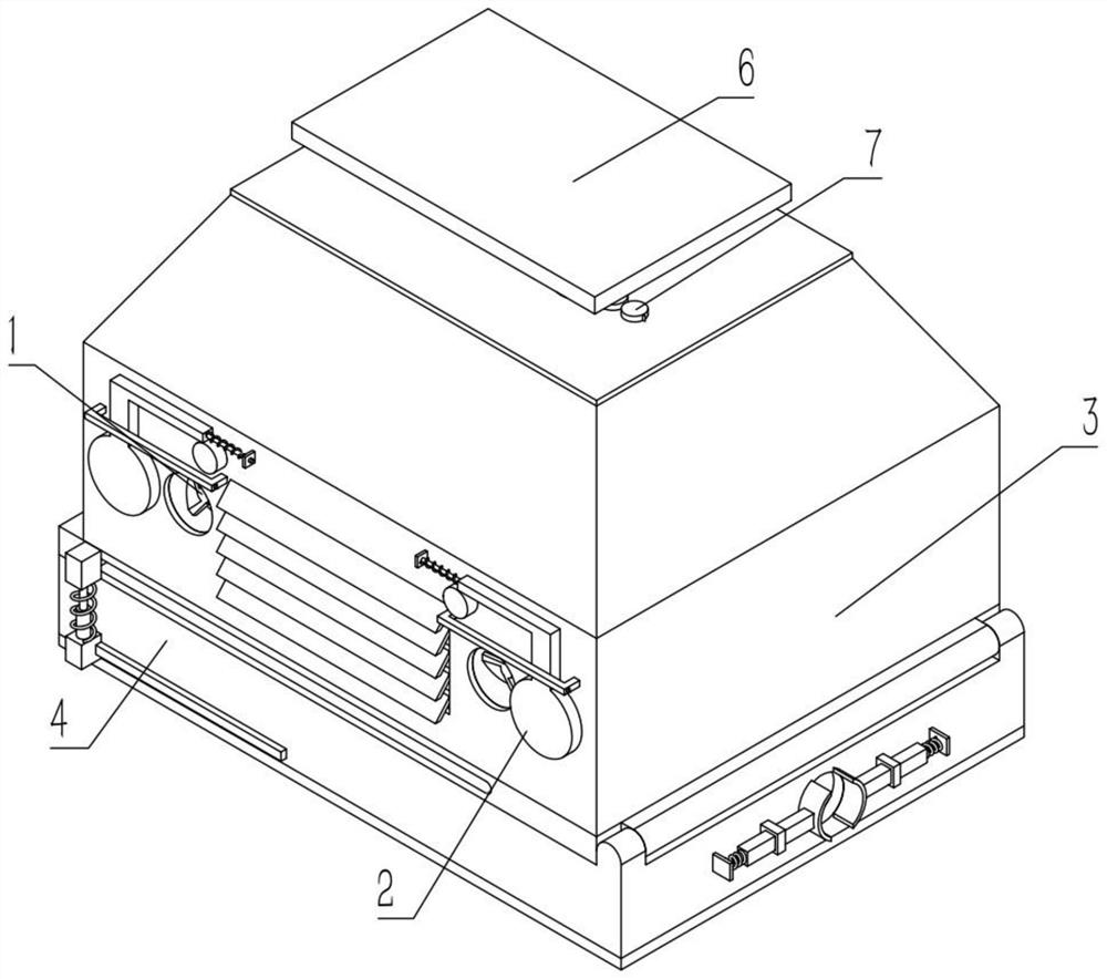
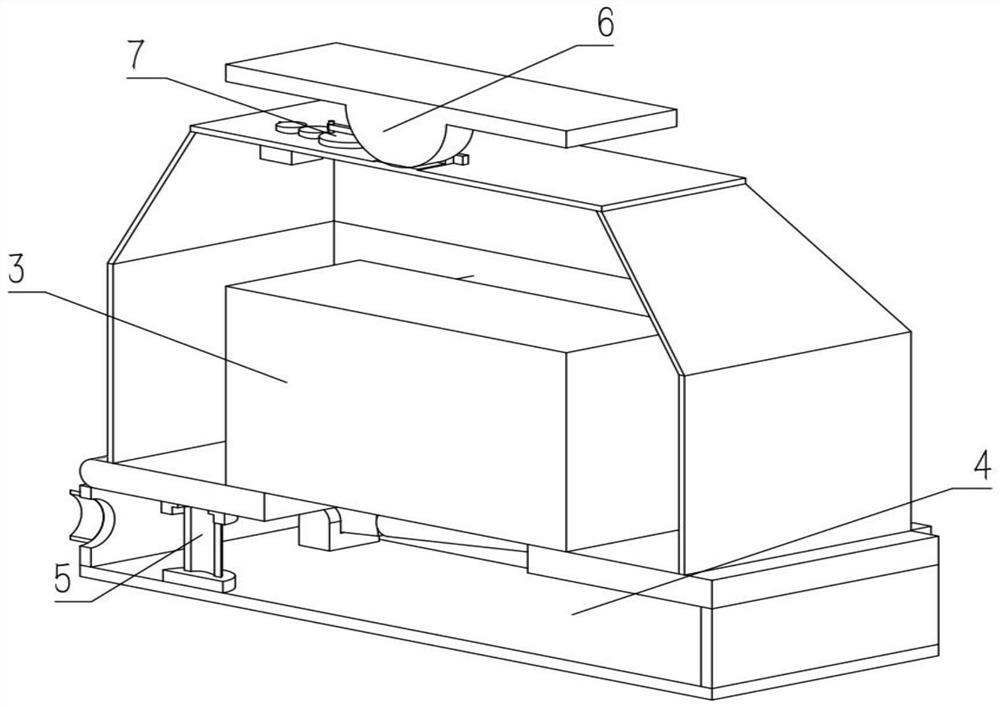
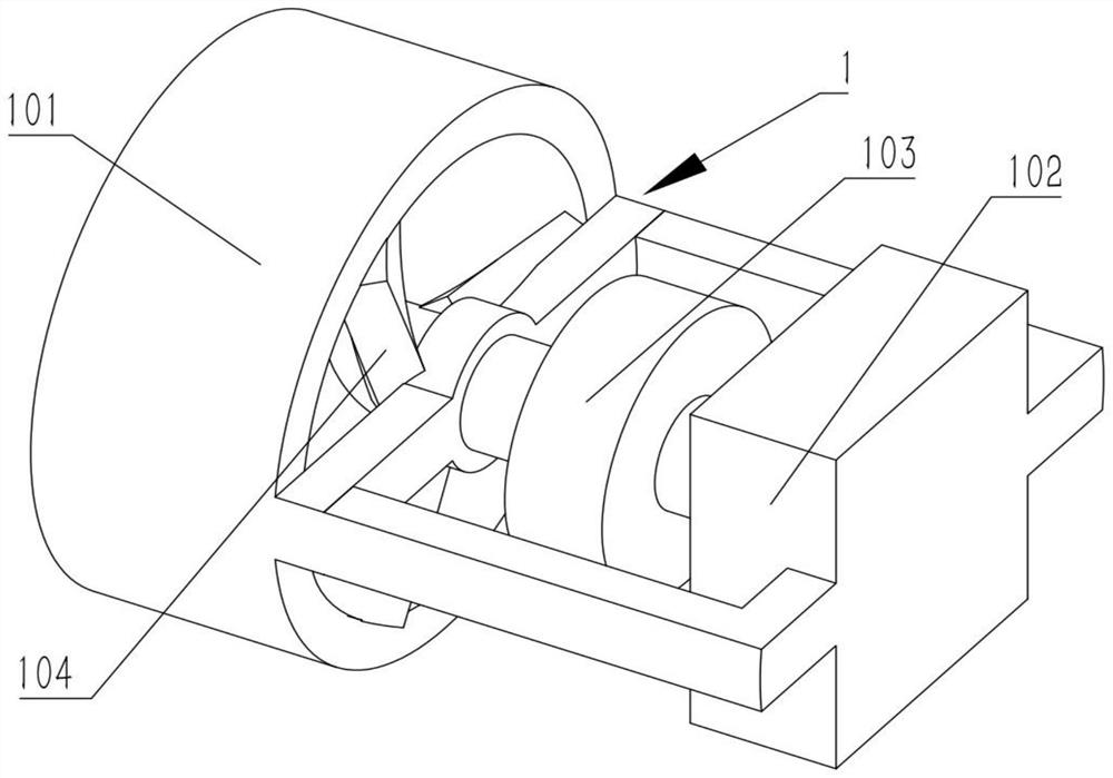
[0029] Combine below Figure 1-9 Describe this embodiment, a power transformer, including a heat dissipation mechanism 1 and a dustproof mechanism 2, the heat dissipation mechanism 1 includes a heat dissipation frame 101, a heat dissipation motor 102, a pulley shaft 103 and fan blades 104, and the heat dissipation motor 102 is fixedly connected to the heat dissipation frame 101, the pulley shaft 103 is fixedly connected to the output shaft of the cooling motor 102, the fan blade 104 is fixedly connected to the left end of the pulley shaft 103, and the pulley shaft 103 is rotatably connected to the heat sink 101, and the dustproof mechanism 2 includes a dustproof plate 201 , the friction rod 202 and the friction wheel 203, the friction rod 202 is fixedly connected to the upper end of the dustproof plate 201, the friction rod 202 and the friction wheel 203 are frictionally driven, and the friction rod 202 is provided with a slide bar;

[0030] This device can quickly and quickly...

specific Embodiment approach 2

[0031] Combine below Figure 1-9 Describe this embodiment, this embodiment will further explain Embodiment 1, the dust-proof mechanism 2 also includes a dust-proof frame 204 and a dust-proof belt wheel shaft 205, the dust-proof plate 201 is slidably connected on the dust-proof frame 204, and the friction wheel 203 Fixedly connected to the dust-proof pulley shaft 205, the multiple dust-proof pulley shafts 205 are driven by belts with multiple pulley shafts 103 respectively;

[0032]Under normal conditions, the dust-proof plate 201 blocks the cooling holes. When cooling is required, the cooling holes are opened to greatly improve the cooling efficiency. The rotation of the output shaft of the cooling motor 102 drives the pulley shaft 103 to rotate, and the rotation of the pulley shaft 103 drives the dust-proof pulley shaft 205 Rotate, the rotation of the dust-proof belt wheel shaft 205 drives the friction wheel 203 to rotate, the rotation of the friction wheel 203 drives the mov...

specific Embodiment approach 3

[0033] Combine below Figure 1-9 Describe this embodiment, this embodiment will further explain the second embodiment, the power transformer also includes a main body mechanism 3, the main body mechanism 3 includes a main body box 301, a main body transformer 302, a main body rotating plate 303, and a main body baffle 304 And the main body heat dissipation hole 305, the main body transformer 302 is fixedly connected on the main body rotating plate 303, a through-wire hole is provided on the main body rotating plate 303, the main body box 301 is fixedly connected on the main body rotating plate 303, and the main body box 301 is provided with A plurality of main body radiating holes 305, the left and right ends of the main body box 301 are provided with a ventilation hole, the left and right ends of the main body box 301 are fixedly connected with a plurality of main body baffles 304, and the plurality of main body baffles 304 are respectively located on the two sides. In each v...


PUM


Abstract

The present invention relates to the technical field of power transformers, more specifically to a power transformer, which includes a heat dissipation mechanism and a dustproof mechanism. The shielding mechanism includes a heat dissipation frame, a heat dissipation motor, a pulley shaft and fan blades. The right end of the pulley shaft is fixedly connected to the output shaft of the cooling motor, the fan blade is fixedly connected to the left end of the pulley shaft, and the pulley shaft is rotatably connected to the cooling frame. The dust-proof mechanism includes a dust-proof plate, a friction rod and a friction wheel, and the friction rod It is fixedly connected to the upper end of the dust-proof plate, and the friction rod and the friction wheel are frictionally driven. There is a sliding rod on the friction rod. This device can quickly and quickly dissipate heat when the temperature of the power transformer is too high to prevent the power transformer from being too high. Close the heat dissipation holes when rapid heat dissipation is not required to prevent a large amount of garbage, dust and small animals from entering the device.

Description

technical field [0001] The invention relates to the technical field of power transformers, in particular to a power transformer. Background technique [0002] For example, the disclosure CN106356181B includes a first connecting rod, a vertical cylinder, a push plate, an air inlet pipe, a first one-way valve, an outlet pipe, a universal wheel, a second one-way valve, a first flexible pipe, a bearing plate, etc.; Universal wheels are symmetrically connected to the left and right sides of the outer bottom, the first cylinder is connected to the left and right sides of the bottom of the moving box, the top of the first cylinder is connected to a load-bearing plate, and the top left side of the left load-bearing plate is connected to the first connecting rod , the right side of the right load-bearing plate is connected with a second connecting rod; the shortcoming of this invention is that it cannot close the heat dissipation hole when the heat dissipation is stopped. Contents ...

Claims


Application Information

Patent Timeline
Patent Type & Authority Patents(China)
IPC IPC(8): H01F27/08H01F27/02
CPCH01F27/08H01F27/025H01F27/02
Inventor 罗露露
Owner 江苏巨能电力设备有限公司
Why Eureka
Try Eureka