Method for analyzing high-speed channel through differential signal mode conversion

A mode conversion and differential signal technology, applied in transmission monitoring, electrical components, transmission systems, etc., can solve problems such as not being able to express transmission channel performance well

Active Publication Date: 2021-04-09
P C B A ELECTRONICS WUXI
View PDF4 Cites 0 Cited by
  • Summary
  • Abstract
  • Description
  • Claims
  • Application Information

AI Technical Summary

Problems solved by technology

[0006] Among them, V P and V n Represents two single-ended signals contained in a pair of differential signals, V comm Indicates the common-mode signal, V diff Represents a differential mode signal. Therefore, during the transmission of a differential signal, there will be a phenomenon in which differential energy is converted to common mode energy. This phenomenon is called mode conversion, and mode conversion is an indicator for evaluating the performance of a transmission channel. , which mainly measures the symmetry of the differential signal channel. The smaller the mode conversion, the better the symmetry of the signal channel, but for a complete signal channel, only judging the mode conversion can not express the performance of the transmission channel well.

Method used


Image

  • Method for analyzing high-speed channel through differential signal mode conversion
  • Method for analyzing high-speed channel through differential signal mode conversion
  • Method for analyzing high-speed channel through differential signal mode conversion

Examples


Embodiment Construction

[0030] The specific embodiments of the present invention will be further described below in conjunction with the accompanying drawings.

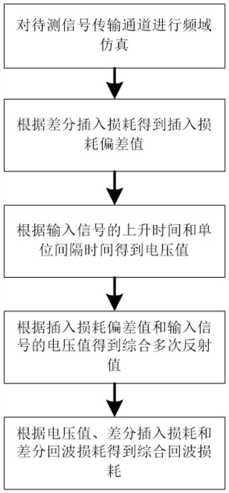
[0031] A method for analyzing high-speed channels through differential signal mode conversion, the method steps are as follows figure 1 shown.

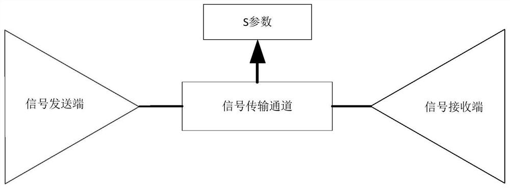
[0032] The signal transmission channel to be tested is simulated in the frequency domain to obtain the S parameters of the signal transmission channel to be tested. The signal transmission channel to be tested refers to a high-speed channel whose rise time of the signal in the channel is less than six times the delay of signal transmission. The full name of the S parameter is The Scatter parameter, that is, the scattering parameter, describes the frequency domain characteristics of the transmission channel. When analyzing the signal integrity of the serial link, it is very important to obtain the accurate S parameters of the transmission channel.

[0033] By analyzing S parameters, signal integrity...


PUM


Abstract

The invention discloses a method for analyzing a high-speed channel through differential signal mode conversion, and relates to the field of signal analysis; the method comprises the steps: carrying out the frequency domain simulation of a to-be-detected signal transmission channel, and obtaining an S parameter of the to-be-detected signal transmission channel; obtaining an insertion loss deviation value according to the differential insertion loss and the differential insertion loss of the reference signal; obtaining a voltage value of the input signal according to the rise time of the input signal and the unit interval time of the input signal; obtaining a comprehensive multiple reflection value according to the insertion loss deviation value and the voltage value of the input signal; obtaining comprehensive return loss according to the voltage value of the input signal, the differential insertion loss and the differential return loss. According to the present invention, the transmission performance of the signal channel is judged by using the comprehensive multiple reflection value and the comprehensive return loss, and the quality of the eye pattern can be evaluated through the sizes of the two parameter indexes while the modal conversion degree of the differential signal in the transmission process can be visually reflected by introducing the new parameter indexes.

Description

technical field [0001] The invention relates to the field of signal channel analysis, in particular to a method for analyzing high-speed channels through differential signal mode conversion. Background technique [0002] Nowadays, the update cycle of electronic equipment is constantly shrinking, and in every signal transmission channel design, it is necessary to continuously improve the integrity of the signal transmission channel. If this problem can be determined as early as possible in the design stage of electronic equipment, it will be greatly improved. Improve the first pass rate of the product and ensure the molding rate of the product. [0003] With the continuous improvement of signal transmission rate, the factors affecting signal integrity are no longer single and independent, and the signal integrity cannot be judged only by the intuition and experience of engineers. Therefore, the simulation technology developed for signal integrity appears to be increasingly i...

Claims


Application Information

Patent Timeline
Patent Type & Authority Applications(China)
IPC IPC(8): H04B17/309
CPCH04B17/309Y02E60/00
Inventor 孙玉明鲁成张洁魏国军简松王志省
Owner P C B A ELECTRONICS WUXI
Why Eureka
Try Eureka