Low profile wideband multibeam integrated dual polarization antenna array with compensated mutual coupling

a dual-polarization, low-profile technology, applied in the direction of antennas, specific program execution arrangements, program control, etc., can solve the problems of affecting the overall performance of the antenna array, techniques that do not work well, etc., to reduce mutual coupling, reduce mutual coupling, and improve the return loss of elements

Inactive Publication Date: 2013-07-18
ULTRA ELECTRONICS TCS
View PDF6 Cites 29 Cited by
  • Summary
  • Abstract
  • Description
  • Claims
  • Application Information

AI Technical Summary

Benefits of technology

[0006]There is described herein a low profile wideband multi-beam integrated dual polarization antenna array with compensated mutual coupling effect. Instead of suppressing mutual coupling with post-element-design techniques by attempting to block the reflections between elements, an element of the array is designed using its active impedance, i.e. its impedance with mutual coup

Problems solved by technology

However, the close proximity of the antenna elements causes significant mutual coupling effects, thereby affecting the overall p

Method used


Image

  • Low profile wideband multibeam integrated dual polarization antenna array with compensated mutual coupling
  • Low profile wideband multibeam integrated dual polarization antenna array with compensated mutual coupling
  • Low profile wideband multibeam integrated dual polarization antenna array with compensated mutual coupling

Examples


Embodiment Construction

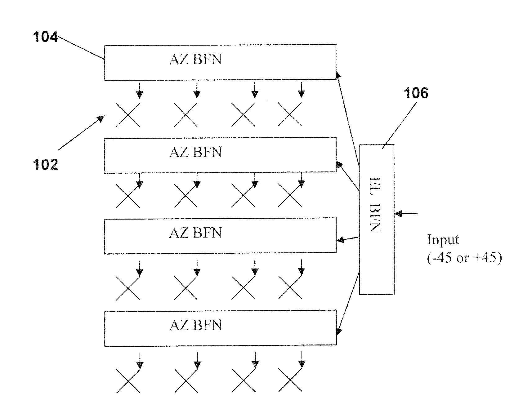
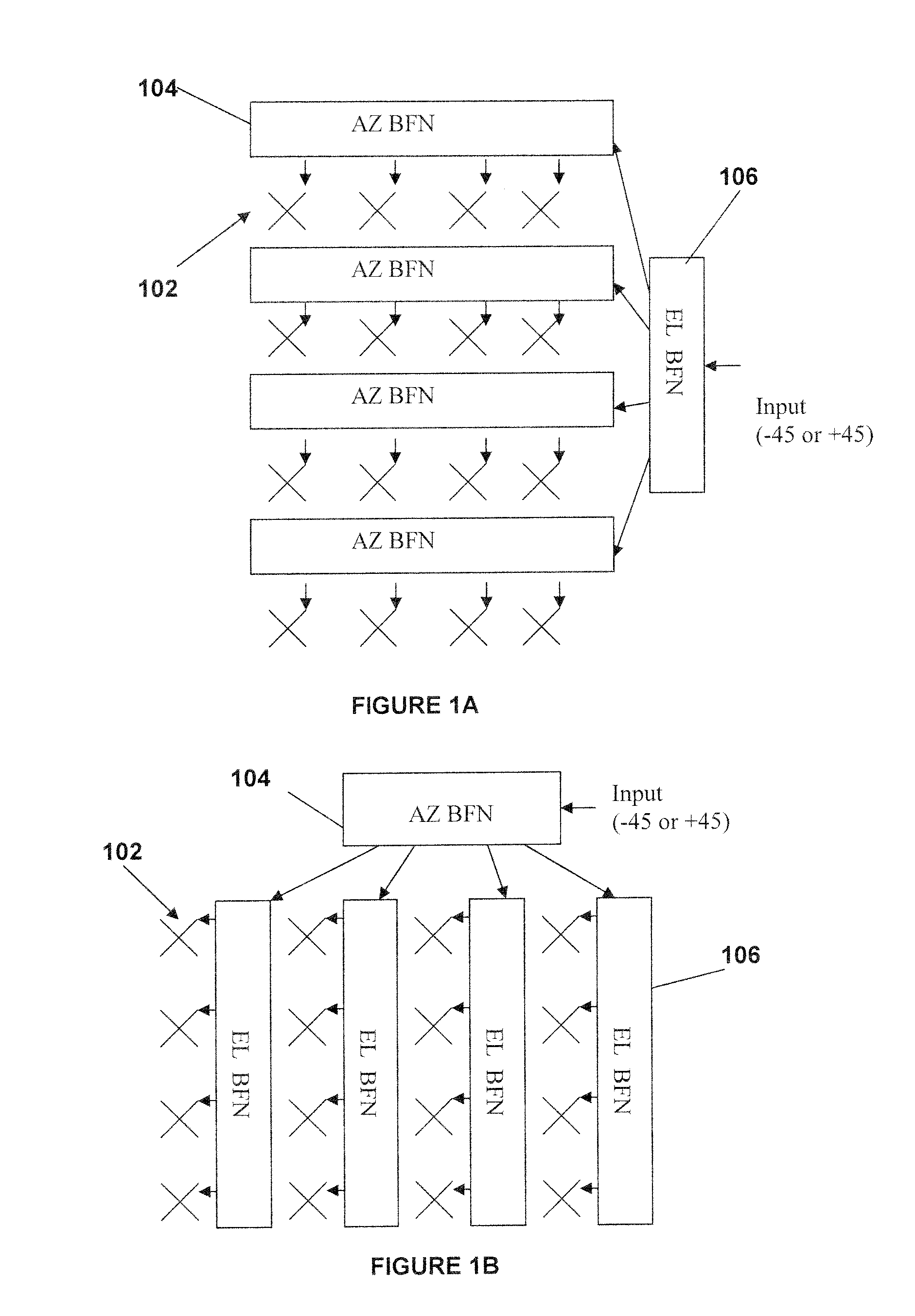
[0025]FIGS. 1A and 1B are example architectures of a planar array with M rows and N columns consisting of three main parts: the antenna elements 102, azimuth beam forming networks (AZ BFN) 104, and an elevation beam forming network (EL BFN) 106. There are two basic structures as shown. FIG. 1A is an example of the planar array (M=4 Rows and N=4 columns) with AZ BFN 104 located between the antenna elements and EL BFN 106, and FIG. 1B is an example of the planar array (M=4 Row and N=4 column) with EL BFN 106 located between the antenna elements and AZ BFN 104. For some arrays with simple functions such as single beam or fixed tilted arrays, the BFN may be as simple as a T-splitter network. For other arrays with more complex functions such as multibeam or variable tilted arrays, the BFN may be a Butler Matrix or a phase shifter. The corresponding architecture is determined based on the functions of the required planar array. In some embodiments, FIG. 1A is used for a variable-tilted ar...


PUM


Abstract

A low profile wideband multi-beam integrated dual polarization antenna array with compensated mutual coupling effect. Instead of suppressing mutual coupling with post-element-design techniques by attempting to block the reflections between elements, an element of the array is designed using its active impedance, i.e. its impedance with mutual coupling once the element is part of the array. The active impedance is determined using various simulation techniques and the element is then designed such that its impedance is shifted in order to modify its active impedance. This technique does not reduce the mutual coupling itself but instead, compensates for the mutual coupling effect and improves the return loss of the element.

Description

CROSS-REFERENCE TO RELATED APPLICATIONS[0001]This is the first application filed for the present invention.TECHNICAL FIELD[0002]The present invention relates to the field of wireless communication systems and antenna arrays suitable for both transmission and reception of electromagnetic radiation.BACKGROUND OF THE ART[0003]Certain designs for antenna arrays consist of closely spaced wideband antenna elements. In order to maintain a small overall size and required antenna performances, such as a wide beam width and a high cross-over point between three individual beams, the spacing between the antenna elements is kept to a minimum (i.e, less than or equal to half a wavelength of a center frequency point). However, the close proximity of the antenna elements causes significant mutual coupling effects, thereby affecting the overall performance of the antenna array.[0004]It is well-known to reduce mutual coupling effects by putting isolators, such as electromagnetic bandgaps (EBGs), bet...

Claims


Application Information

Patent Timeline
IPC IPC(8): H01Q21/00G06F17/50
CPCH01Q1/523
Inventor SHEN, LIN-PINGTRIGUI, HAFEDHDEAN, STUART JAMESYAN, BING
Owner ULTRA ELECTRONICS TCS
Why Eureka
Try Eureka