Dual Polarized Microstrip Antenna

A microstrip antenna and dual-polarization technology, applied in antennas, antenna coupling, antenna arrays, etc., to achieve the effect of improved isolation, good isolation, and high gain

Active Publication Date: 2022-01-18
RADIAWAVE TECH CO LTD
View PDF0 Cites 0 Cited by
  • Summary
  • Abstract
  • Description
  • Claims
  • Application Information

AI Technical Summary

Problems solved by technology

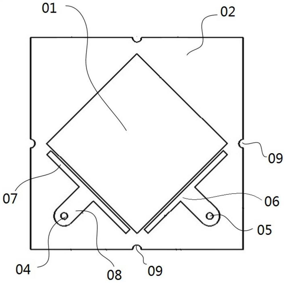
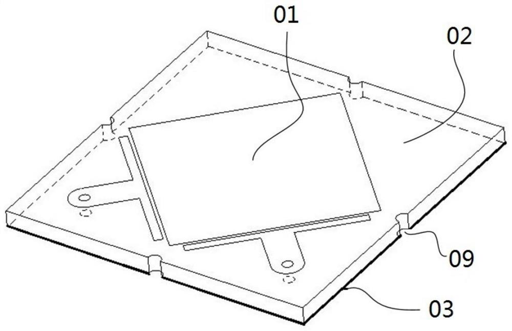
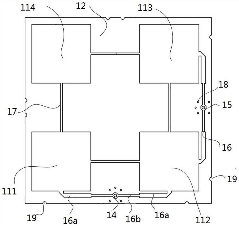
[0004] The main purpose of the present invention is to provide a dual-polarized microstrip antenna, which aims to solve the problem of suppressing mutual coupling of antennas and improving isolation under the condition of miniaturization of antenna structure size

Method used


Image

  • Dual Polarized Microstrip Antenna
  • Dual Polarized Microstrip Antenna
  • Dual Polarized Microstrip Antenna

Examples


Embodiment Construction

[0035] The following will clearly and completely describe the technical solutions in the embodiments of the present invention with reference to the accompanying drawings in the embodiments of the present invention. Obviously, the described embodiments are only part of the embodiments of the present invention, not all of them. Based on the embodiments of the present invention, all other embodiments obtained by persons of ordinary skill in the art without creative efforts fall within the protection scope of the present invention.

[0036] It should be noted that if there is a directional indication (such as up, down, left, right, front, back...) in the embodiment of the present invention, the directional indication is only used to explain the position in a certain posture (as shown in the accompanying drawing). If the specific posture changes, the directional indication will also change accordingly.

[0037] In addition, if there are descriptions involving "first", "second" and ...


PUM


Abstract

The invention discloses a dual-polarized microstrip antenna. The dual-polarized microstrip antenna mainly includes a radiation patch main body, a dielectric substrate and a common ground plane. The dielectric substrate has an upper surface and a lower surface oppositely arranged, and the radiation patch main body On the upper surface of the dielectric substrate, the common ground plate is arranged on the lower surface of the dielectric substrate, and the dual-polarized microstrip antenna provided by the present invention is respectively fed on two adjacent and orthogonal sides of the radiation patch main body, The invention realizes that the mutual coupling of the antenna is suppressed and the isolation degree is improved under the condition of miniaturization of the structure size of the antenna.

Description

technical field [0001] The invention relates to the field of antenna design, in particular to a dual-polarized microstrip antenna. Background technique [0002] In recent years, wireless communication technology has developed rapidly, and antenna, as an important part of a wireless communication system, its performance directly affects the communication quality of the entire communication system. The dual-polarized antenna is the focus of research. [0003] In many practical applications, antennas are usually found in pairs in transceiver wireless systems. Since adjacent antennas are prone to mutual coupling, mutual coupling will deteriorate the antenna’s transceiver isolation, reduce system channel capacity, introduce scanning blind spots, and affect system design accuracy. Generally, blocking methods, long-distance layout, etc. are commonly used in the prior art. method to suppress mutual coupling and improve antenna isolation, in which the blocking method mainly blocks ...

Claims


Application Information

Patent Timeline
Patent Type & Authority Patents(China)
IPC IPC(8): H01Q1/38H01Q1/48H01Q1/50H01Q1/52H01Q15/24H01Q21/00H01Q21/06
CPCH01Q1/38H01Q1/48H01Q1/50H01Q1/52H01Q1/523H01Q15/24H01Q21/0006H01Q21/065
Inventor 丁青龙冯海刚张宁檀聿麟戴思特
Owner RADIAWAVE TECH CO LTD
Why Eureka
Try Eureka