Multiband Common Aperture Antenna

A common aperture, antenna technology, applied in leaky waveguide antennas, antennas, antenna arrays and other directions, can solve problems such as strong mutual coupling, the influence of antenna radiation efficiency, and the inability to suppress surface waves of common aperture antennas

Active Publication Date: 2018-03-13
HUAWEI TECH CO LTD
View PDF5 Cites 0 Cited by
  • Summary
  • Abstract
  • Description
  • Claims
  • Application Information

AI Technical Summary

Problems solved by technology

[0004] An embodiment of the present invention provides a multi-band common-aperture antenna to overcome the problem that the surface wave of the common-apertu

Method used


Image

  • Multiband Common Aperture Antenna
  • Multiband Common Aperture Antenna
  • Multiband Common Aperture Antenna

Examples


Embodiment Construction

[0031] In order to make the purpose, technical solutions and advantages of the embodiments of the present invention clearer, the technical solutions in the embodiments of the present invention will be clearly and completely described below in conjunction with the drawings in the embodiments of the present invention. Obviously, the described embodiments It is a part of embodiments of the present invention, but not all embodiments. Based on the embodiments of the present invention, all other embodiments obtained by persons of ordinary skill in the art without creative efforts fall within the protection scope of the present invention.

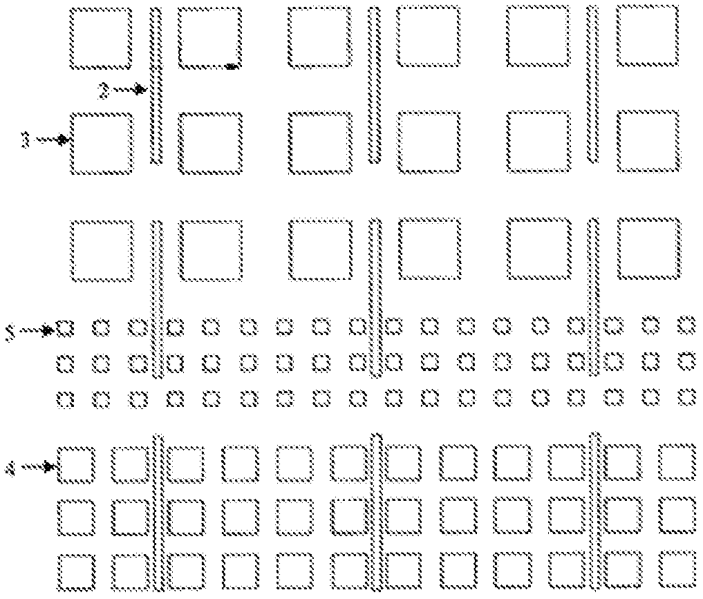
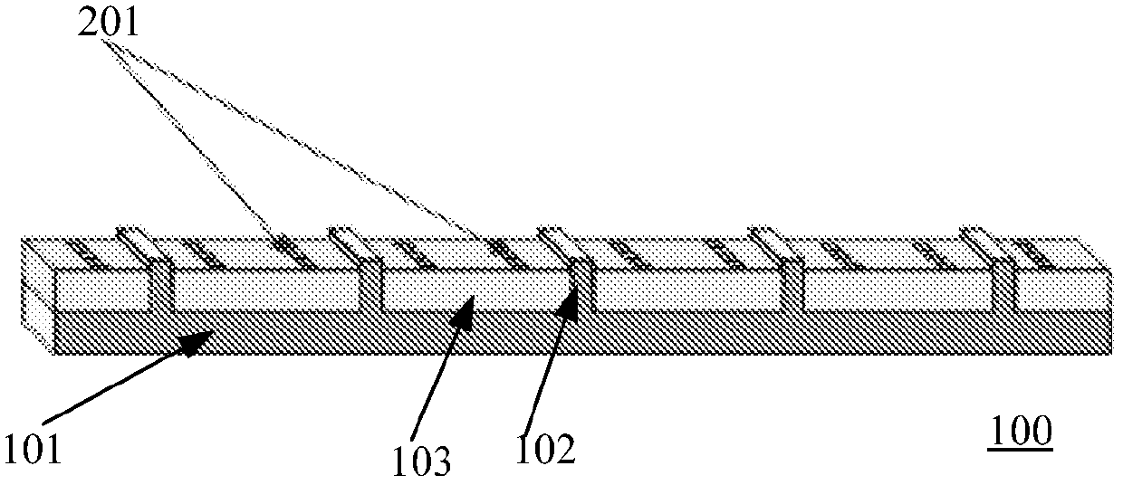
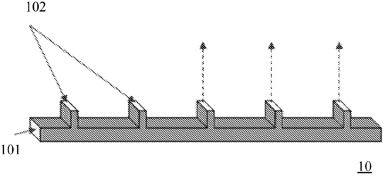
[0032] figure 2 It is a schematic diagram of the overall structure of Embodiment 1 of the multi-band co-aperture antenna of the present invention. image 3 It is a schematic diagram of the overall structure of the CTS antenna according to Embodiment 1 of the present invention. Figure 4 It is a schematic diagram of a cross-sectional structure o...


PUM


Abstract

An embodiment of the present invention provides a multiband common-caliber antenna. The multiband common-caliber antenna of the present invention comprises a continuous transverse stub (CTS) antenna and a microstrip patch antenna. The CTS antenna comprises a planar waveguide feeding structure and multiple strip-shaped waveguide radiation units disposed on the planar waveguide feeding structure and disposed in a spaced manner along a first direction. A medium substrate is disposed between every two strip-shaped waveguide radiation units and on the upper surface of the planar waveguide feeding structure. Microstrip patch antenna arrays are disposed on the upper surface of the medium substrate. Each of the microstrip patch antenna arrays comprises multiple microstrip patch antenna units disposed in a spaced manner along a second direction perpendicular to the first direction. The number of the microstrip patch antenna arrays disposed on at least one of the medium substrate is not less than 2. The microstrip patch antenna arrays disposed on the medium substrates form the microstrip patch antenna. The embodiment of the present invention suppresses mutual coupling between surface waves of the microstrip patch antenna and the antenna.

Description

technical field [0001] Embodiments of the present invention relate to communication technologies, and in particular to a multi-band common-aperture antenna. Background technique [0002] With the rapid development of wireless communication, a communication system is required to have multiple functions, so a matching dual-band or multi-band radiation and receiving system is required. However, in many communication devices, due to the requirements of device integration and miniaturization, there is not enough space allocated to two or more antennas of different bands. In order to realize the integrated design of antennas of different bands in a limited space, it is necessary to design the antennas of different bands on the same aperture to realize the sharing of apertures. Common-aperture dual-frequency or multi-frequency antennas are also required to reduce equipment costs, improve equipment integration, and promote intelligent antenna integration. [0003] figure 1 It is ...

Claims


Application Information

Patent Timeline
IPC IPC(8): H01Q13/08
CPCH01Q1/523H01Q13/28H01Q21/065H01Q21/205
Inventor 杜明德蔡华
Owner HUAWEI TECH CO LTD
Why Eureka
Try Eureka