Sub-wavelength antenna array with defected ground structure for time reversal communication

A defect-based structure and antenna array technology, applied in antenna arrays, antennas, electrical components, etc., can solve the problems of reduced communication capacity and communication rate of mobile terminal systems, limited size of mobile terminal platforms, and increased coupling between units. Realize the effect of convenience, improved communication capacity, and small mutual coupling

Inactive Publication Date: 2013-07-17
UNIV OF ELECTRONICS SCI & TECH OF CHINA
View PDF3 Cites 0 Cited by
  • Summary
  • Abstract
  • Description
  • Claims
  • Application Information

AI Technical Summary

Problems solved by technology

If the distance between the antenna units is much smaller than half the working wavelength in a limited space, the coupling between the units will increase, and the correlation of the wireless channels corresponding to each antenna will be greatly improved, resulting in a significant reduction in the communication capacity and communication rate of the mobile terminal system. , seriously impairs the communication quality, thus losing the meaning of introducing a multi-antenna system
Although people have done a lot of research on the miniaturization of antenna units, due to the limited size of the mobile terminal platform, integrating multiple antennas for different channels on the mobile terminal still takes up a lot of space

Method used


Image

  • Sub-wavelength antenna array with defected ground structure for time reversal communication
  • Sub-wavelength antenna array with defected ground structure for time reversal communication
  • Sub-wavelength antenna array with defected ground structure for time reversal communication

Examples


Embodiment Construction

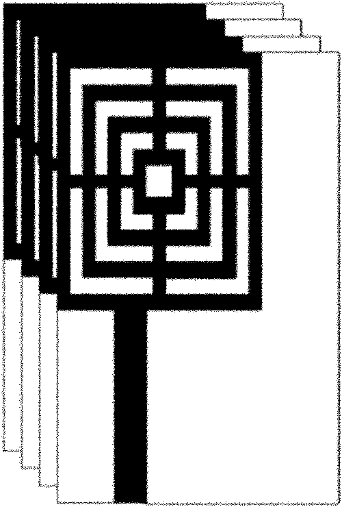
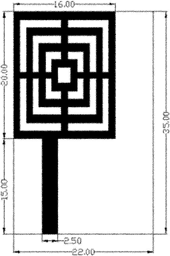
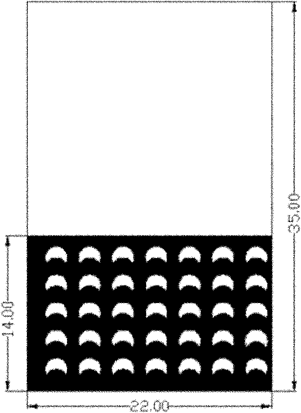
[0025] A defective ground-structure subwavelength antenna array for time-reversal communication, such as figure 1 As shown, it is formed by stacking multiple identical antenna elements, and the distance between two adjacent element antennas is less than 1 / 2 of the working wavelength λ. Each antenna unit such as figure 2 , 3 As shown, it includes a rectangular dielectric substrate and metal patches on the front and back of the rectangular dielectric substrate.

[0026] The metal patch on the front of the rectangular dielectric substrate is as figure 2 As shown, it includes a radiating unit in the shape of a concentric rectangular ring cluster and a microstrip feeder with a characteristic impedance of 50 ohms. In the cluster of concentric rectangular rings, the perimeter of the largest rectangular ring is λ / 10:λ / 5, and the perimeters of other rectangular rings are indented inward at a ratio of 25%, and the center of any adjacent two sides adopts a line width of λ / 100:λ / 50...


PUM


Abstract

The invention discloses a sub-wavelength antenna array with a defected ground structure for time reversal communication, belonging to the technical field of wireless communication. The sub-wavelength antenna array is formed by stacking a plurality of same antenna units, and the distance between two adjacent unit antennae is smaller than 1 / 2 working wavelength lambda. A metal patch in the front ofa medium substrate comprises radiating units in the shape of a concentric rectangular ring cluster. In the concentric rectangular ring cluster, the perimeter of the maximum rectangular ring is lambda / 10:lambda / 5, the perimeters of other rectangular rings are sequentially shortened inwards in a proportion of 25%, and centers of any two adjacent sides are connected by adopting a microstrip line with the line width of lambda / 100:lambda / 50. The radiating units carry out feeding by adopting a microstrip line with the characteristic impedance of 50 ohms. A metal patch at the back of the medium substrate is a metal floor in which 35 crescent holes are etched uniformly. The sub-wavelength antenna array disclosed by the invention is applied to a time domain mobile communication terminal of time reversal, all channels of the antenna units are relatively independent and have small cross coupling, the interference between adjacent channels is extremely low, and the sub-wavelength antenna array can support higher data transmission ratio and frequency spectrum utilization ratio.

Description

technical field [0001] The invention belongs to the technical field of wireless communication, and relates to an antenna array whose spacing between antenna elements works at a sub-wavelength, and in particular to a time-reversal sub-wavelength antenna array for a wireless mobile terminal. Background technique [0002] Improving the communication capacity and communication rate of the mobile communication system is the goal pursued by mobile communication. With the continuous growth of personal service requirements, mobile terminals are faced with a huge demand for urgent improvement in communication capacity and communication rate. Designing multiple antenna units on the mobile terminal and increasing the number of independent wireless channels is one of the main means for future mobile communications to improve the communication performance of mobile terminals [0003] According to the traditional theory, in order to make the multi-antenna system obtain good space diversi...

Claims


Application Information

Patent Timeline
Patent Type & Authority Patents(China)
IPC IPC(8): H01Q21/00
Inventor 王秉中章志敏葛广顶
Owner UNIV OF ELECTRONICS SCI & TECH OF CHINA
Why Eureka
Try Eureka