
Seismic Data Acquisition System and Method for Downhole Use

a seismic data and data acquisition technology, applied in the field of seismic systems, can solve the problems of inability to change the configuration, inability to detect the polarity and amplitude of a waveform in three dimensions, and often limited borehole seismic recording, so as to improve the data transfer rate and improve the accuracy of borehole seismic recording

Inactive Publication Date: 2006-01-19
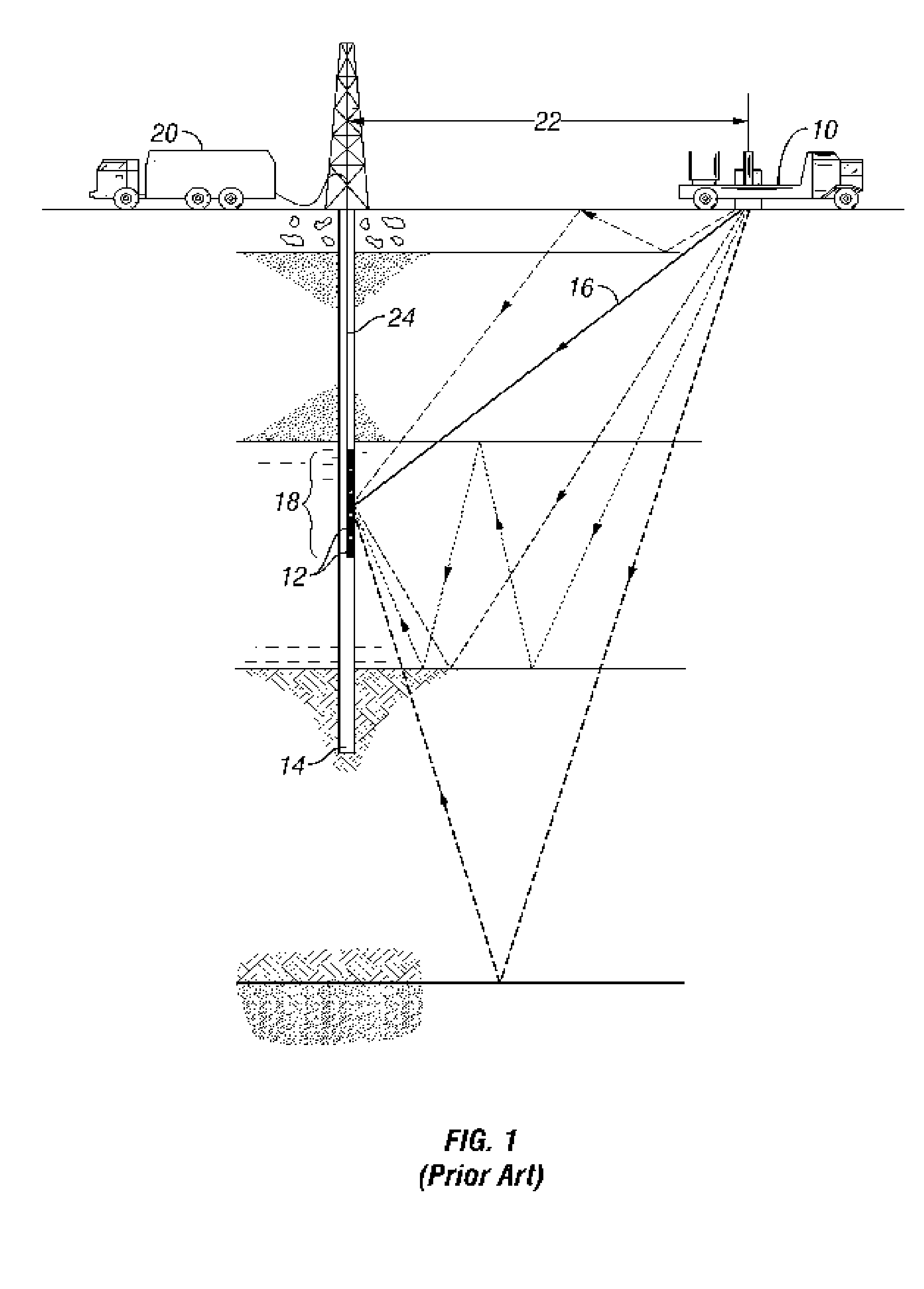
SENSORWISE
View PDF14 Cites 59 Cited by
  • Summary
  • Abstract
  • Description
  • Claims
  • Application Information

AI Technical Summary

Benefits of technology

[0021] A primary object of the invention is to provide a method and system for improved borehole seismic measurement by improving data transfer rates between the downhole components in an array of intelligent sensors.
[0025] Another object of the invention is to provide a method and system for a seismic array having a varying number or type of sensors located therein, the sensors having connectors to allow interconnection in varying numbers and with varying lengths of cable, thus allowing easy configuration changes and array repair in the field.

Problems solved by technology

Because of the widespread preference for surface-recorded seismic surveys, borehole seismic recording has often been limited to the velocity check-shot survey, a method used to determine seismic velocities over various intervals in the well for interpretation of surface recorded seismic data.
Receivers are often simple pressure transducers and are incapable of detecting the polarity and amplitude of a waveform in three dimensions.
Thus, the array configuration is generally fixed; it is not possible to change the configuration at the job site, and field repairs are limited.
It is advantageous to record measurements over the whole vertical range of the well to provide the most complete depth and coverage, but it is also more costly.
One major inefficiency of the borehole seismic process is the need for each downhole multi-component receiver to be clamped to the borehole wall.
The clamping and unclamping process takes time.
However, these receivers provide only single component data which limits subsurface imaging and seismic data extraction, because compression (P) and shear (S) data cannot be resolved.
Additionally, because the receivers are free-hanging, borehole waves are a major source of noise.
Although some of this noise can be removed with various filtering operations, free-hanging sensors do not image as deep as their clamped-geophone counterparts.
The large capital invested in seven-conductor cable and equipment may make a transition to another cable type cost prohibitive.
The long length reduces the available bandwidth of the databus.
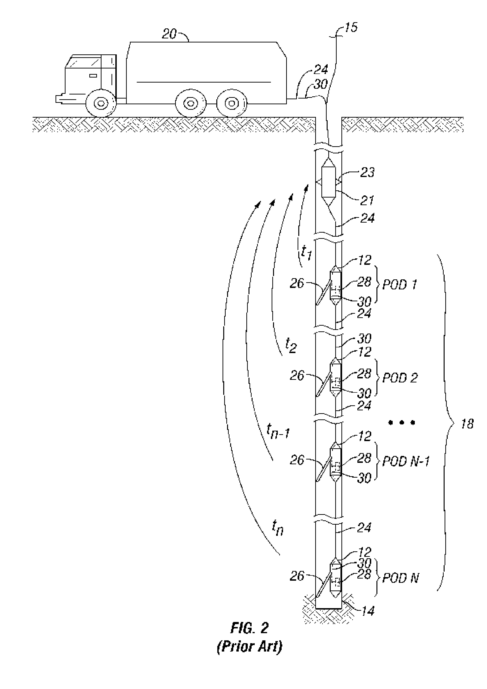
As the number of receivers continues to rise, the large data volumes which must be transmitted to the receiver before the array can be repositioned, bottlenecked by the insufficient bandwidth of the databus, becomes significant.
In addition to the obstacle of overcoming the inertia of the capital investment in seven-conductor wireline cable, as discussed earlier, fiber optics are problematic from a materials standpoint because of the high downhole temperatures encountered.

Method used


Image

  • Seismic Data Acquisition System and Method for Downhole Use
  • Seismic Data Acquisition System and Method for Downhole Use
  • Seismic Data Acquisition System and Method for Downhole Use

Examples


Embodiment Construction

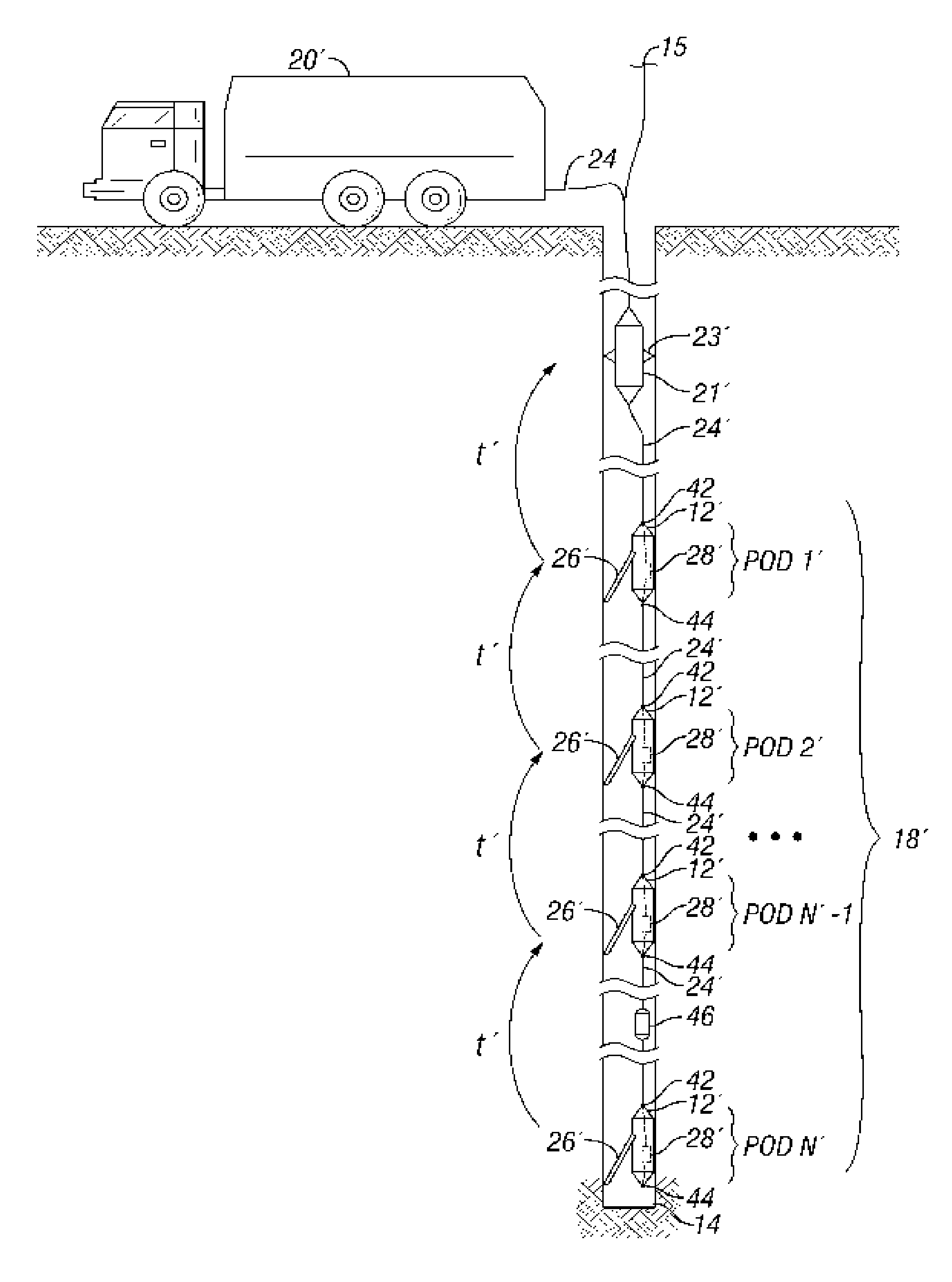
[0041]FIG. 4 illustrates a borehole seismic recording system according to the invention. The system includes a surface-based main controller 20′ connected to a telemetry and control module 21′, which is in turn connected to one end of a string 18′ of multiple remote measurement stations, or pods, 12′ that are interconnected serially by cables 24′ and quick-disconnect connectors 42, 44. The telemetry and control module 21′ and the string 18′ are lowered into a borehole 14 and suspended by a winch 15. Because the pods are interconnected in the array 18′ using releasable connectors instead of e.g., overmolding, the pods 12′ and the cable segments 24′ are easily removed from the array for repair. In fact, the array can be field modified to suit particular requirements by adding or removing pods, shifting sensor depths (by substituting cable segments with differing lengths), or substituting pods with different sensor types. Each pod 12′ which is equipped with sensors, e.g., 3-C sensors, ...


PUM


Abstract

A method and system for conducting a seismic survey by lowering a string of intelligent clampable sensor pods with 3-C sensors into a borehole. The string of pods is serially interconnected by a cable having a conductor pair which provides both power and data connectivity. The uppermost sensor pod is connected to a downhole telemetry and control module. The cables and pods use connectors to allow assembly, customization, repair, and disassembly on site. Each pod has an upper and a lower connector, a processor, and memory which is coupled to both the upper and the lower connectors. Each pod is capable of simultaneous and independent serial communications at each connector with the memory. The telemetry and control module is designed to query the pods to determine the system configuration. The telemetry and control module then simultaneously triggers all pods to acquire data, the pods storing the collected data locally in the memory. After data collection, the controller simultaneously signals the pods to immediately transfer data serially from the local memory to the next higher adjacent pod and receive data, if any, from the lower adjacent pod, if any, storing the received data in memory. The first data transferred from each pod is that data collected by its local sensors. Subsequent data originates from lower pods and is simply passed up the string of pods to the telemetry and control module. In other words, the pods communicate in a bucket brigade fashion.

Description

BACKGROUND OF THE INVENTION [0001] 1. Field of the Invention [0002] This invention relates generally to seismic systems, and more particularly to seismic systems used in the hydrocarbon exploration and mining industries. Specifically, this invention relates to a system and method for transmitting data from remote measuring stations in a vertical seismic profiling or cross-well seismic profiling toolset. [0003] 2. Description of the Prior Art [0004] Measuring seismic data in boreholes has origins which can be traced back to 1917, where the technology was introduced in U.S. Pat. No. 1,240,328 issued to Fessenden. Because of the widespread preference for surface-recorded seismic surveys, borehole seismic recording has often been limited to the velocity check-shot survey, a method used to determine seismic velocities over various intervals in the well for interpretation of surface recorded seismic data. [0005] A typical check shot survey involves lowering a geophone or hydrophone into a...

Claims


Application Information

Patent Timeline
Patent Type & Authority Applications(United States)
IPC IPC(8): G01V1/00G08C19/16G01V3/00G08B1/00
CPCG01V11/002
Inventor VARSAMIS, GEORGIOS L.WISNIEWSKI, LAURENCE T.ARIAN, ABBAS
Owner SENSORWISE
Learn More