Oscilloscope based return loss analyzer

a return loss analyzer and oscilloscope technology, applied in the field of signal acquisition systems, can solve the problems of tdr oscilloscopes and dedicated software packages adapted to compute time domain parameters and convert these parameters into frequency domain parameters more difficult to use than conventional network analyzers, and the use of oscilloscopes within the context of network analyzer functions has been deemed susp

Active Publication Date: 2007-09-18
TEKTRONIX INC
View PDF10 Cites 29 Cited by
  • Summary
  • Abstract
  • Description
  • Claims
  • Application Information

AI Technical Summary

Problems solved by technology

Return loss measurements, and other measurements within the context of, illustratively, 1000BaseT (gigabit Ethernet) performed as a function of frequency are typically made using network analyzers, which tend to be very expensive.
However, it is generally perceived that the combination of TDR oscilloscopes and dedicated software packages adapted to compute the time domain parameters and convert these parameters into frequency domain parameters are more difficult to use than conventional network analyzers.
The use of oscilloscopes within the context of network analyzer functions has also been deemed suspect due to the nominal 8-bit dynamic range of standard analog-to-digital converters used in oscilloscopes.

Method used


Image

  • Oscilloscope based return loss analyzer
  • Oscilloscope based return loss analyzer
  • Oscilloscope based return loss analyzer

Examples


Embodiment Construction

[0015]The subject invention is primarily described within the context of a test setup or system using one or more digital storage oscilloscopes (DSOs) having spectral analysis functionality. However, it is understood by those skilled in the art that the invention may be advantageously employed using any signal measurement or analysis devices in which the below-described functionality is included. The subject invention is well suited to performing differential return loss measurements and other measurements as a function of frequency within, for example, the context of Infiniband, 1000BaseT and other serial data standards.

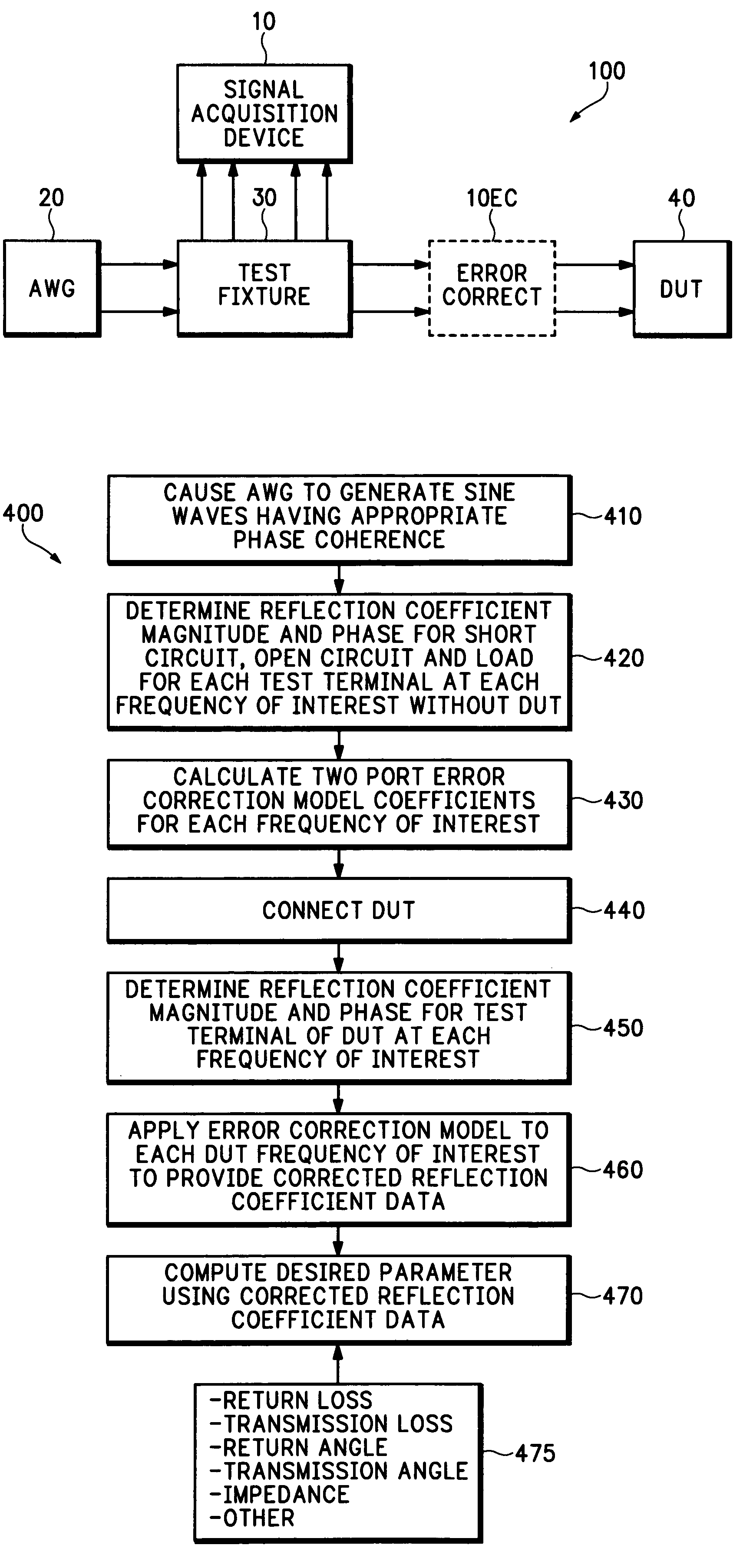
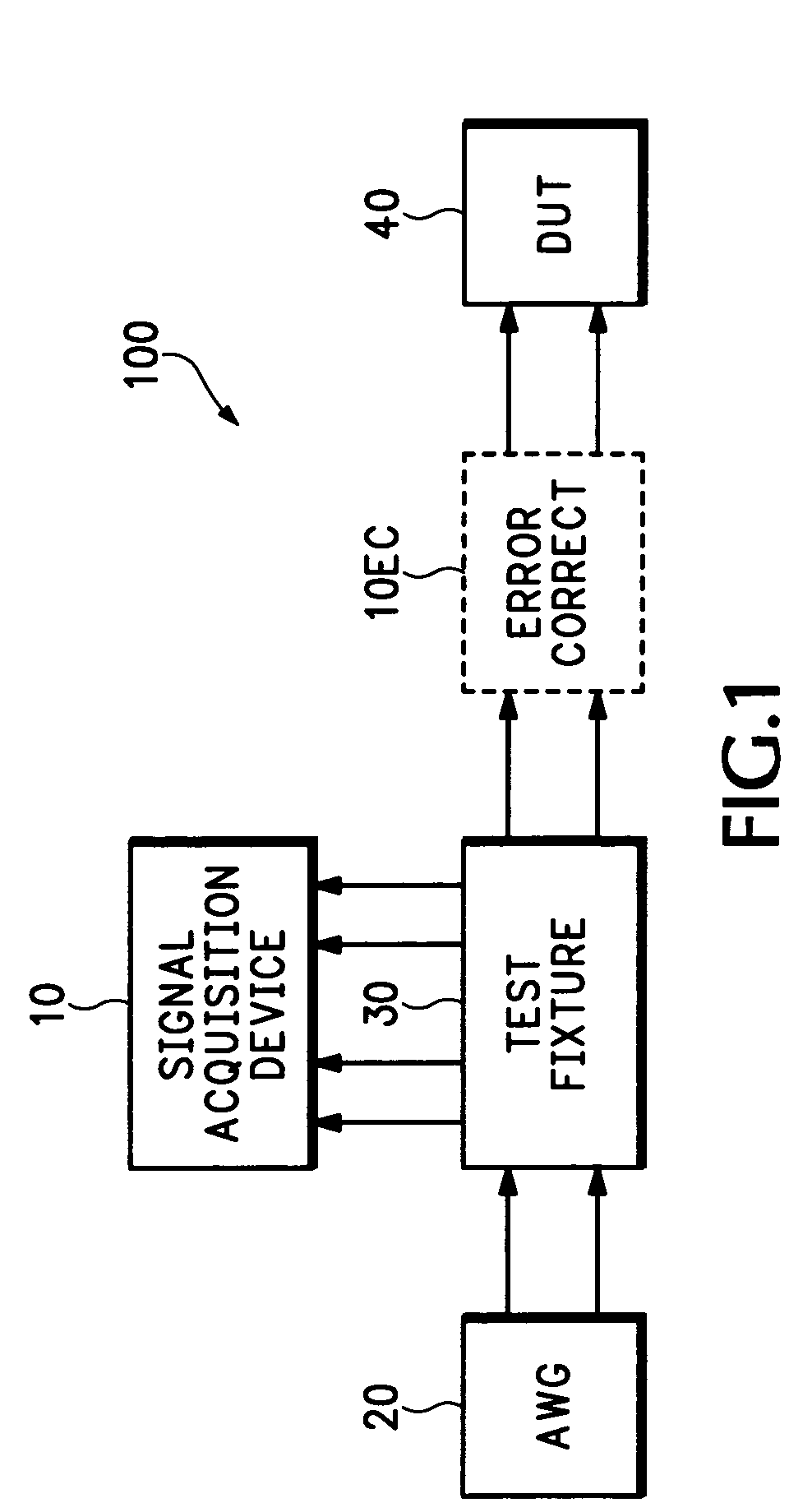
[0016]FIG. 1 depicts a high level block diagram of a test system 100 according to an embodiment of the invention. Specifically, the test system 100 of FIG. 1 has an arbitrary waveform generator (AWG) 20 which provides a differential test signal of an arbitrary waveform having signal energy at each of a plurality of frequencies of interest to a test fixture 30. Test ...


PUM


Abstract

A system, apparatus and method for performing differential return loss measurements and other measurements as a function of frequency uses a digital storage oscilloscope (DSO) having spectral analysis functions. A waveform generator generates a differential test signal in the form of a series of pulses where each pulse includes spectral components associated with each of a plurality of frequencies of interest. A test fixture presents the differential test waveform to a load including at least one of a device under test (DUT), a short circuit, an open circuit and a balanced load. A signal acquisition device differentially measures the test waveform during each of the load conditions. The signal acquisition device computes an error correction parameter using measurements made during the short circuit, open circuit and balanced load conditions. The correction parameter tends to offset signal acquisition errors within measurements made during the DUT load condition.

Description

CROSS-REFERENCE TO RELATED APPLICATIONS[0001]This patent application claims the benefit of U.S. Provisional Patent Application Ser. No. 60 / 401,903, filed on Aug. 7, 2002, for OSCILLOSCOPE BASED RETURN LOSS ANALYZER, which is incorporated herein by reference in its entirety.FIELD OF THE INVENTION[0002]The invention relates generally to signal acquisition systems and, more particularly, to a system, apparatus and method enabling an oscilloscope to perform differential return loss and other measurements as a function of frequency.BACKGROUND OF THE INVENTION[0003]Return loss measurements, and other measurements within the context of, illustratively, 1000BaseT (gigabit Ethernet) performed as a function of frequency are typically made using network analyzers, which tend to be very expensive. To reduce total cost, one network analyzer work station is often shared by multiple oscilloscope work stations within the context of a testing environment. As an alternative, time division reflectomet...

Claims


Application Information

Patent Timeline
Patent Type & Authority Patents(United States)
IPC IPC(8): G01R23/00G01R23/16G01R27/06G01R13/22
CPCG01R13/22
Inventor PICKERD, JOHN J.DOUBRAVA, LAUDIE J.
Owner TEKTRONIX INC
Why Eureka
Try Eureka