Adjustable trigger voltage pulse width control method

A technology of pulse width control and trigger voltage, applied in the field of optics, can solve the problems that cannot be easily changed, the controller cannot trigger and control the light source, etc., and achieves the effect of novel idea, reasonable design and strong anti-interference ability.

Pending Publication Date: 2021-04-09
东莞锐视光电科技有限公司
View PDF0 Cites 0 Cited by
  • Summary
  • Abstract
  • Description
  • Claims
  • Application Information

AI Technical Summary

Problems solved by technology

[0003] In view of the fact that the above-mentioned existing trigger control can only use a fixed range of trigger voltage, when there is interference or other problems on site, it cannot be easily changed when the low-voltage or high-voltage trigger needs to be replaced, and the controllers currently on the market cannot pass the identification of the pulse width. And set the trigger pulse width condition to trigger the technical problem of controlling the light source

Method used


Image

  • Adjustable trigger voltage pulse width control method
  • Adjustable trigger voltage pulse width control method

Examples


Embodiment Construction

[0016] Below in conjunction with accompanying drawing and embodiment the present invention will be further described:

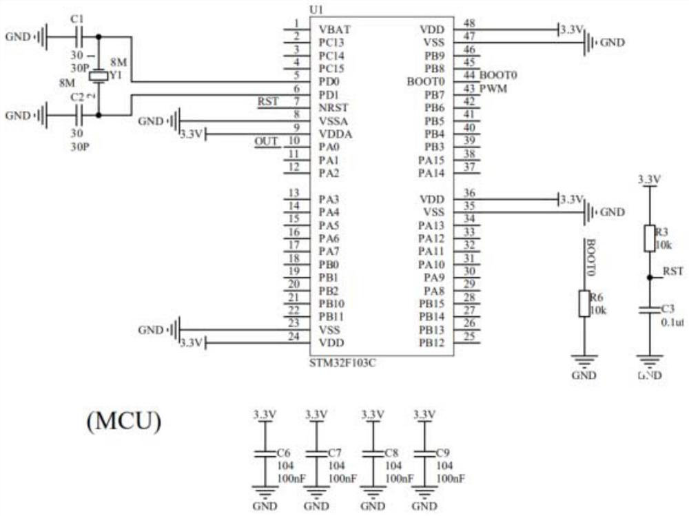
[0017] like Figure 1-Figure 2 As shown, an adjustable trigger voltage pulse width control circuit, including:

[0018] A single-chip microcomputer is used for the control of the light source, and sends pulse width modulation signals and receives trigger signals;

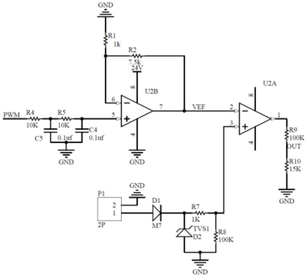
[0019] A digital-to-analog conversion circuit for receiving the pulse width modulation signal sent by the single-chip microcomputer and converting it into an analog signal;

[0020] An amplifying circuit, used to amplify the analog signal output by the digital-to-analog conversion circuit and output it as a reference voltage VEF;

[0021] The first amplifier receives the reference voltage VEF and the comparison voltage, and outputs a signal voltage to the single-chip microcomputer after comparison;

[0022] An anti-reverse polarity protection circuit is used to connect to the amplifier and provi...


PUM


Abstract

The invention discloses an adjustable trigger voltage pulse width control method. The method comprises the following steps: 1, sending an initial pulse width modulation signal through a single chip microcomputer; 2, enabling the initial pulse width modulation signal to enter a digital-to-analog conversion circuit, and converting a digital signal into an analog signal to be output; 3, externally connecting the analog signal obtained in step 2 with an amplification voltage through an amplification circuit; and connecting the first amplifier with an anti-reverse connection protection circuit; and 4, enabling the first amplifier to compare the reference voltage signal with the comparison voltage signal and then output a trigger signal needing to be sent to a single-chip microcomputer. According to the invention, the pulse width modulation signal output by the single-chip microcomputer is amplified into the reference voltage after digital-to-analog conversion, and if the trigger voltage is relatively low and the required speed is relatively high, the reference voltage can be lowered and the input pulse width can be set to be small; nd reference voltage is adjusted and input pulse width is set separately according to actual needs so as to achieve stronger anti-interference capability.

Description

technical field [0001] The invention relates to the field of optical technology, in particular to an adjustable trigger voltage pulse width control method. Background technique [0002] Currently on the market for machine vision light source controllers, the trigger control can only use a fixed range of trigger voltage. When there is interference or other problems on site, it cannot be easily changed when the low voltage or high voltage trigger needs to be replaced, and the controllers currently on the market cannot By identifying the pulse width, and setting the trigger pulse width condition to trigger and control the light source. Contents of the invention [0003] In view of the fact that the above-mentioned existing trigger control can only use a fixed range of trigger voltage, when there is interference or other problems on site, it cannot be easily changed when the low-voltage or high-voltage trigger needs to be replaced, and the controllers currently on the market c...

Claims


Application Information

Patent Timeline
Patent Type & Authority Applications(China)
IPC IPC(8): H05B47/165H05B47/26
CPCH05B47/165H05B47/26
Inventor 王晶晶黄勇肖金荣邓启路黎立文
Owner 东莞锐视光电科技有限公司
Why Eureka
Try Eureka