Gantry multi-point welding machine

A welding machine and multi-point technology, applied in the direction of welding equipment, auxiliary welding equipment, welding/cutting auxiliary equipment, etc., can solve the problems of increasing cost, reducing production quality, and surface damage of workpieces, so as to reduce iron slag content and improve Recycling process, the effect of increasing the degree of push

Pending Publication Date: 2021-04-13
杨康艺
View PDF0 Cites 0 Cited by
  • Summary
  • Abstract
  • Description
  • Claims
  • Application Information

AI Technical Summary

Problems solved by technology

[0003] In the process of realizing the present invention, the inventors have found that at least the following problems have not been solved in the prior art: 1. The existing gantry multi-point welding machine is also called a mesh welding machine, and small iron slag can be produced in the welding process of the welding machine It falls on the conveyor table, which is inconvenient to clean. When the next workpiece to be welded is placed, it will cause damage to the surface of the workpiece, damage the product, and reduce the quality of production; 2. Iron slag on the conveyor table during welding It will cause the welding head to press the workpiece during spot welding, causing the workpiece to move and cause welding errors, which makes the workpiece scrapped, increases the production cost, and reduces the production efficiency; 3. Some small welding machines in the prior art, in the workpiece welding process It also needs to be manually fixed, and it needs to be manually disassembled and moved after the welding is completed.

Method used


Image

  • Gantry multi-point welding machine
  • Gantry multi-point welding machine
  • Gantry multi-point welding machine

Examples


Embodiment Construction

[0028] The following will clearly and completely describe the technical solutions in the embodiments of the present invention with reference to the accompanying drawings in the embodiments of the present invention. Obviously, the described embodiments are only some, not all, embodiments of the present invention. Based on the embodiments of the present invention, all other embodiments obtained by persons of ordinary skill in the art without making creative efforts belong to the protection scope of the present invention.

[0029] see Figure 1 to Figure 6 , the present invention provides a technical solution:

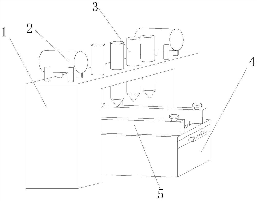
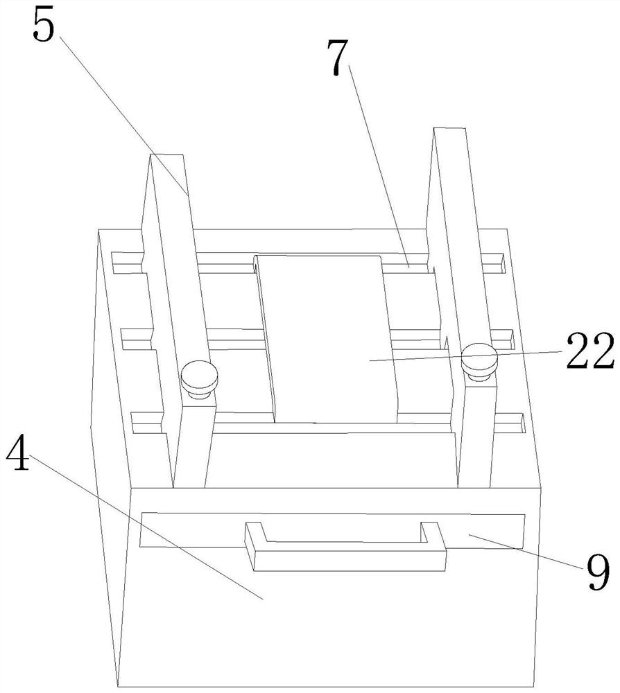
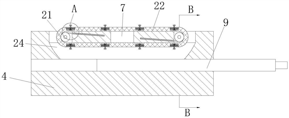
[0030] A gantry multi-point welding machine, such as figure 1 As shown, it includes a bracket 1 and a delivery platform 4, the delivery platform 4 is located below the bracket 1, the upper outer surface of the bracket 1 is fixedly connected with a tank body 2, and the upper outer surface of the bracket 1 is slidably connected with a welding head 3 The outer surface of t...


PUM


Abstract

The invention discloses a gantry multi-point welding machine which comprises a support and a conveying platform. The conveying platform is located below the support, tank bodies are fixedly connected to the outer surface of the upper end of the support, welding heads are connected to the outer surface of the upper end of the support in a sliding mode, and sliding grooves are formed in the outer surface of the upper end of the conveying platform. Baffles are connected to the outer surface of the upper end of the conveying platform in a sliding mode, fixing bolts are rotationally connected to the outer surfaces of the upper ends of the baffles, rectangular grooves are formed in the outer surfaces of the lower ends of the baffles, and push plates are fixedly connected to the inner surfaces of the rectangular grooves. According to the gantry multi-point welding machine, a workpiece on the conveying platform can be prevented from being scraped by iron slag, the iron slag on the spot welding machine can be effectively cleaned away, a conveying strip can be kept clean and is convenient to use, the baffles on the conveying platform can effectively clamp the workpiece, the stability of the workpiece is guaranteed, the phenomenon that welding errors happen due to movement of the workpiece in the welding process is avoided, and the working efficiency is guaranteed.

Description

technical field [0001] The invention relates to the field of welding technology, in particular to a gantry multi-point welding machine. Background technique [0002] The gantry multi-point welding machine is also called a welding mesh machine. It needs a kind of pressure to complete the purpose of welding. Whether it is from the formation process of solder joints or from some welding joints, it is relatively simple in welding. [0003] In the process of realizing the present invention, the inventors have found that at least the following problems have not been solved in the prior art: 1. The existing gantry multi-point welding machine is also called a mesh welding machine, and small iron slag can be produced in the welding process of the welding machine It falls on the conveyor table, which is inconvenient to clean. When the next workpiece to be welded is placed, it will cause damage to the surface of the workpiece, damage the product, and reduce the quality of production; 2...

Claims


Application Information

Patent Timeline
IPC IPC(8): B23K37/00B23K37/04
CPCB23K37/00B23K37/0435
Inventor 杨康艺毕少华
Owner 杨康艺
Why Eureka
Try Eureka