
Mechanical arm

A robotic arm and arc-shaped block technology, applied in the field of robotic arms, can solve the problem of inconvenient number of claws of the robotic arm.

Active Publication Date: 2021-04-13
JINAN BIOBASE BIOTECH
View PDF5 Cites 1 Cited by
  • Summary
  • Abstract
  • Description
  • Claims
  • Application Information

AI Technical Summary

Problems solved by technology

[0006] Therefore, the technical problem to be solved by the present invention is that the number of jaws of the existing robotic arm is inconvenient to properly convert as the shape of the grasped item changes.

Method used


Image

  • Mechanical arm
  • Mechanical arm
  • Mechanical arm

Examples


Embodiment 1

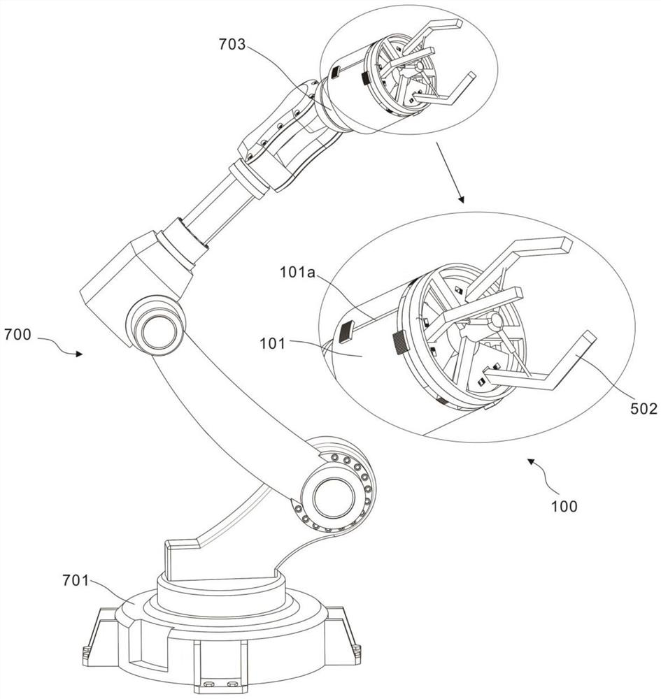
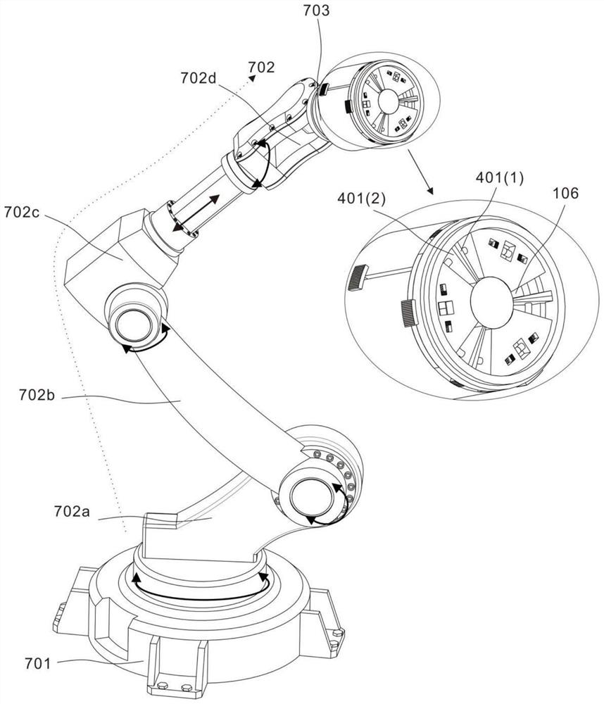
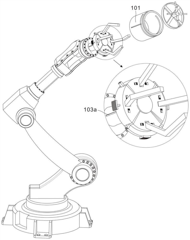
[0039] refer to Figure 1-8 , this embodiment provides a mechanical arm, including a support assembly 700, including a base 701, a steering piece 702 and a grabbing hand 703, the steering piece 702 is connected to the base 701 and the grabbing hand 703, and the end of the grabbing hand 703 is provided with arm end 100;

[0040] The steering member 702 includes a first rotating member 702a, a second rotating member 702b, a telescopic member 702c and a swinging member 702d. One end of the first rotating member 702a is axially connected to the end face of the base 701, and the side of the second rotating member 702b is connected to one end of the first rotating member 702a. The side faces are connected with a shaft, one side of the telescopic part 702c is connected with the side of the second rotating part 702b with a shaft, and the swing part 702d is connected with the other end of the telescopic part 702c with a shaft.

[0041] figure 2 shows the movable direction of the fir...


PUM


Abstract

The invention discloses a mechanical arm. The mechanical arm comprises a supporting assembly and a mechanical arm end .The supporting assembly comprises a base, a steering part and a grabbing hand, the steering part is connected with the base and the grabbing hand, and the end of the grabbing hand is provided with an arm end; and the mechanical arm end comprises an end shell, a cavity is formed in the end shell, a supporting shaft is arranged in the middle of the interior of the end shell, and the supporting shaft and the end shell are coaxially arranged. According to a mechanical claw, the number of clamping claws can be adjusted so as to adapt to the shape of a grabbed object.

Description

technical field [0001] The invention relates to the technical field of mechanical devices, in particular to a mechanical arm. Background technique [0002] The mechanical claw refers to a high-precision, high-speed glue dispensing robot arm. The mechanical claw is a complex system with multiple inputs and multiple outputs, a high degree of nonlinearity, and strong coupling. Because of its unique operational flexibility, it has been widely used in industrial assembly, safety and explosion-proof fields. [0003] Mechanical claws are usually used to grab items, especially in the automatic production line. When grabbing items in the production line, the shape of some items will make it difficult for the mechanical claws to grab the number of front claws. For example, cube items, three The mechanical claws of claws are difficult to grasp, so it is necessary to design a mechanical claw that is easy to change the number of claws to meet the grasping needs of items on the productio...

Claims


Application Information

Patent Timeline
Patent Type & Authority Applications(China)
IPC IPC(8): B25J15/00B25J15/10
CPCB25J15/0028B25J15/10
Inventor 刘瑞徐林
Owner JINAN BIOBASE BIOTECH
Learn More