Water discharging device for gas extraction pipeline

A technology of gas drainage and water release device, which is applied in the direction of gas discharge, valves for ventilation, valve operation/release devices, etc., and can solve the problems of spontaneous combustion and ignition of boreholes, increased resistance of gas drainage, gas combustion or explosion, etc. problem, to achieve the effect of reducing labor intensity, improving extraction efficiency, and simple structure

Active Publication Date: 2021-04-13
华能煤炭技术研究有限公司
View PDF10 Cites 0 Cited by
  • Summary
  • Abstract
  • Description
  • Claims
  • Application Information

AI Technical Summary

Problems solved by technology

[0002] During the coal mine gas extraction process, the extraction system is in a negative pressure state, and the water in the borehole or the water vapor condensate in the gas gas will enter the extraction pipeline, and the water will gather in the low-lying part of the pipeline to cause drainage. Pipeline water blockage affects the normal operation of the drainage system, increases gas drainage resistance, and reduces the gas drainage effect
At the same time, when coal seams that are spontaneously combustible or prone to spontaneous combustion are extracted, there is a risk of spontaneous combustion and ignition in the borehole. The high temperature or sparks generated by spontaneous combustion can easily cause gas combustion or explosion when entering the extraction system, which brings great hidden dangers to the safe mining of coal mines.
[0003] In order to prevent combustion or explosion of the extracted gas, in the prior art, the inlet pipe of the gas extraction pipeline is usually submerged into the water to realize fire and explosion protection, but there are still the following disadvantages: the water release device does not have the function of automatically releasing water, resulting in water discharge The pressure in the device increases, the resistance of gas drainage increases, and the efficiency of gas drainage decreases; manual water discharge, the technical problem of high labor intensity for the operator

Method used


Image

  • Water discharging device for gas extraction pipeline

Examples


Embodiment Construction

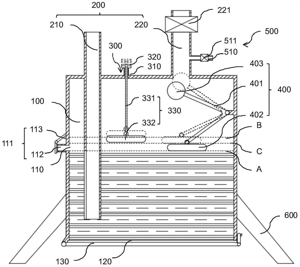
[0042] In order to make the above-mentioned purposes, features and advantages of the present invention more obvious and understandable, the following in conjunction with the attached figure 1 Specific embodiments of the present invention are described in detail, figure 1 The automatic pressure relief component 300 shown in the solid line and the second water level detection component 400 shown in the solid line represent a schematic diagram of the working state of the drainage pipeline, and the automatic pressure relief component 300 shown in the dotted line and the second water level shown in the dotted line The detection part 400 is a schematic diagram showing the state of automatic water release.

[0043] In the present invention, the terms "inner", "outer", "upper", "lower", etc. indicating orientation or positional relationship are based on the orientation or positional relationship shown in the drawings, and are only for the convenience of describing the present inventio...


PUM


Abstract

The invention relates to a water discharging device for a gas extraction pipeline. The water discharging device comprises a water tank, the gas extraction pipeline and an automatic pressure relief component. A water discharging opening is formed in the middle of the water tank in the height direction, and a blocking piece is arranged at the water discharging opening. The gas extraction pipeline is connected with the water tank. The gas extraction pipeline comprises a gas inlet pipe and a gas outlet pipe, wherein a gas outlet end of the gas inlet pipe can be immersed into water, and a gas inlet end of the gas outlet pipe is located above the water in the water tank. The automatic pressure relief component comprises an automatic pressure relief pipe, an automatic pressure relief pipe cover and a first water level detection component. The automatic pressure relief pipe is connected with the water tank, and the automatic pressure relief pipe cover is arranged above the automatic pressure relief pipe. The first water level detection component is configured to enable the automatic pressure relief pipe cover to open the automatic pressure relief pipe when water in the water tank rises to a first water level, wherein the first water level is higher than the lowest position of the water discharging opening. According to the water discharging device for the gas extraction pipeline, automatic water discharging of the water discharging device is achieved, smooth gas extraction is guaranteed, the gas extraction efficiency is improved, and the labor intensity of an operator is relieved.

Description

technical field [0001] The invention relates to the technical field of gas drainage in coal mines, in particular to a water release device for a gas drainage pipeline. Background technique [0002] During the coal mine gas extraction process, the extraction system is in a negative pressure state, and the water in the borehole or the water vapor condensate in the gas gas will enter the extraction pipeline, and the water will gather in the low-lying part of the pipeline to cause drainage. Pipeline water blockage will affect the normal operation of the drainage system, increase the resistance of gas drainage and reduce the effect of gas drainage. At the same time, when extracting spontaneously or easily spontaneously combustible coal seams, there is a risk of spontaneous combustion and ignition in the borehole. The high temperature or sparks generated by spontaneous combustion can easily cause gas combustion or explosion when entering the drainage system, which brings major hid...

Claims


Application Information

Patent Timeline
Patent Type & Authority Applications(China)
IPC IPC(8): E21F7/00E21F16/00F16K24/04F16K31/20
CPCE21F7/00E21F16/00F16K24/042F16K31/20
Inventor 栗磊张倩李伟东汪义龙孙晓虎李永元沙兴锋栗伟王维刘杰殷裁云崔宝库何健
Owner 华能煤炭技术研究有限公司
Why Eureka
Try Eureka