
10kv column type porcelain bottle wire self-locking device

A self-locking device, 1.10kv technology, applied in the direction of adjusting/maintaining mechanical tension, etc., to avoid excessively long transmission lines, improve insulation, and reduce shaking

Active Publication Date: 2022-06-17
海南电网有限责任公司昌江供电局 +1
View PDF0 Cites 0 Cited by
  • Summary
  • Abstract
  • Description
  • Claims
  • Application Information

AI Technical Summary

Problems solved by technology

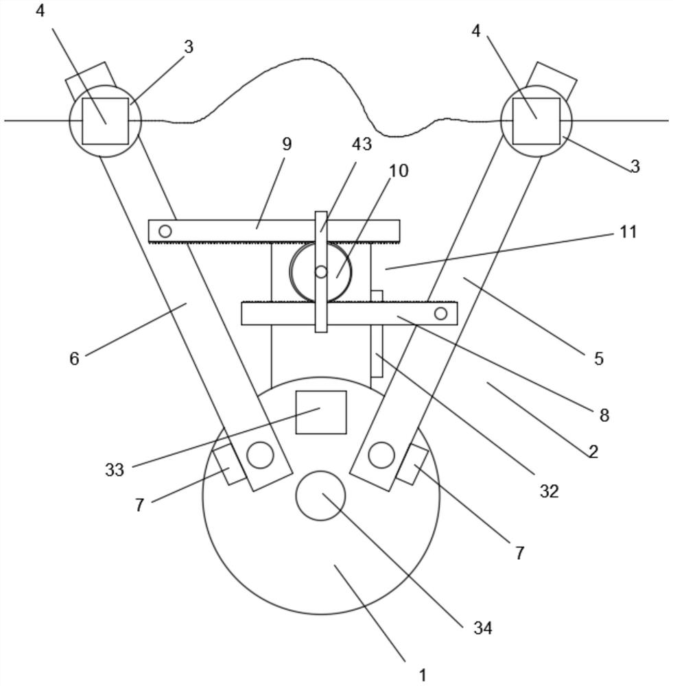
[0003] Aiming at the above prior art, the present invention is to provide a self-locking device for 10kV column type porcelain bottle wire, which can self-lock in both directions. The line is locked tightly, so it is not easy to cause the reserved length of the transmission line to be too long. At the same time, the transmission line is tightened in typhoon weather, reducing the shaking of the transmission line after being blown by the wind, and weakening the fatigue damage of the transmission line

Method used


Image

  • 10kv column type porcelain bottle wire self-locking device
  • 10kv column type porcelain bottle wire self-locking device
  • 10kv column type porcelain bottle wire self-locking device

Examples


Embodiment 1

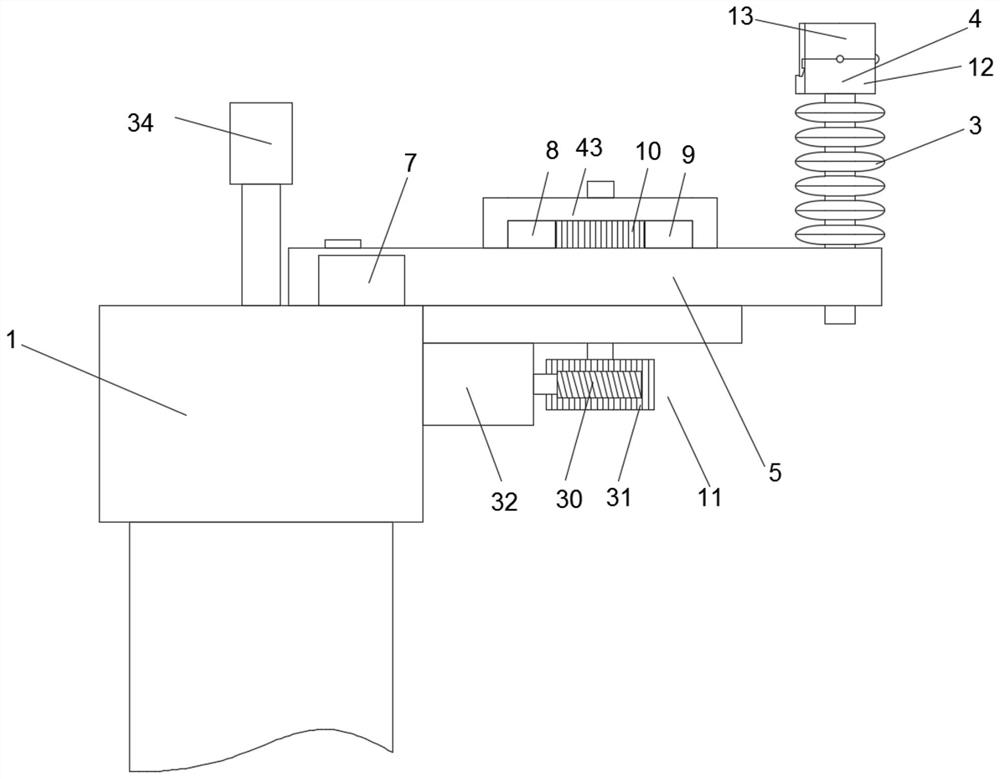
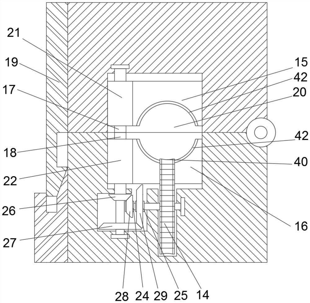
[0026] see Figures 1 to 5 , 10kV column-type porcelain bottle wire self-locking device, including base 1, adjusting cross arm 2, insulator 3 and holder 4; the base 1 is used to connect with the transmission pole, and the base 1 is connected with the adjustment Cross-arm 2; Described adjustment cross-arm 2 includes first cross-arm 5 and second cross-arm 6, and described first cross-arm 5 and second cross-arm 6 are respectively connected to the base 1 in rotation, and the base 1. There is a limit block 7 that restricts the rotation angle of the first cross arm 5 and the second cross arm 6, the first cross arm 5 is rotatably connected with the first rack 8, and the second cross rail is rotatably connected with the first rack 8. Two racks 9, the base 1 is provided with a first gear 10 that meshes with the first rack 8 and the second rack 9 at the same time, the base 1 is provided with a drive to drive the first gear 10 to rotate Mechanism 11; the first cross arm 5 and the second...

Embodiment 2

[0035] see Figures 6 to 7 The difference between this embodiment and Embodiment 1 is that the driving mechanism 11 includes a first windward plate 35, a second windward plate 36 and a windshield frame 37, and an opening of one end of the windshield frame 37 is provided with a first windward plate 35, the other end opening is provided with a second windward plate, the first windward plate and the second windward plate 36 are respectively slidably connected to the base 1, and the first windward plate 35 and the second windward plate are parallel to the transmission line , the first windward plate 35 is provided with a third rack 38, the second windward plate 36 is provided with a fourth rack 39, and the third rack 38 and the fourth rack 39 are respectively engaged with the A gear 10 on both sides. The first windward plate and the second windward plate 36 are respectively slidably connected to the base 1 . Optionally, the first windward plate and the second windward plate 36 ar...


PUM


Abstract

The invention discloses a 10kV column-type porcelain bottle wire self-locking device, which includes a base, an adjusting cross arm, an insulator and a clamper; the base is used to connect with a power transmission pole, and the base is connected with the adjusting cross arm; Both the first cross arm and the second cross arm are provided with the insulator, and the top of the insulator is provided with a clamp; the clamp is used to fix the transmission line. In the present invention, after clamping the transmission line into the clamper, the transmission line is reciprocally pulled in the clamper at the fixed point of the transmission line, so as to lock the transmission line, and it is not easy to cause the reserved length of the transmission line to be too long. In typhoon weather, the transmission line is tightened to reduce the shaking of the transmission line after being blown by the wind, and to reduce the fatigue damage of the transmission line.

Description

technical field [0001] The invention relates to the technical field of a wire self-locking device, in particular to a wire self-locking device for a 10kV cylindrical porcelain bottle. Background technique [0002] In the operation of 10kV distribution line, when using binding wire to fix, the binding wire often breaks, causing the transmission line to fall off on the cross arm and cause the line grounding fault. The other insulated wires are bound with binding wire, especially in coastal areas with high humidity. , discharge phenomenon often occurs, and users are often appealed when crossing residential areas. When using self-locking device to fix, because the self-locking device is one-way self-locking, it is easy to cause the reserved length of the transmission line to be too long after the transmission line is fixed. , the transmission line sags down a lot, and in the environment of strong wind in typhoon weather, the transmission line shakes greatly after being blown by ...

Claims


Application Information

Patent Timeline
Patent Type & Authority Patents(China)
IPC IPC(8): H02G7/02
CPCH02G7/02
Inventor 韩梓鹏邢维标郭教研陈子乐吴师同宋键
Owner 海南电网有限责任公司昌江供电局
Learn More