Coil holder for receiving field winding of rotor, and motor having such coil holder

A technology of coil support and excitation winding, which is applied in the direction of winding, electrical components, electromechanical devices, etc. It can solve the problems that the coil support is not fixed, the filling resin does not reach the excitation winding sufficiently, and achieve the effect of improving insulation and preventing fatigue

Pending Publication Date: 2021-04-13
SEG AUTOMOTIVE GERMANY GMBH
View PDF1 Cites 0 Cited by
  • Summary
  • Abstract
  • Description
  • Claims
  • Application Information

AI Technical Summary

Problems solved by technology

[0004] Another problem with electric motors is that the coil supports are not optimally fixed relative to the claw p...

Method used


Image

  • Coil holder for receiving field winding of rotor, and motor having such coil holder
  • Coil holder for receiving field winding of rotor, and motor having such coil holder
  • Coil holder for receiving field winding of rotor, and motor having such coil holder

Examples


Embodiment Construction

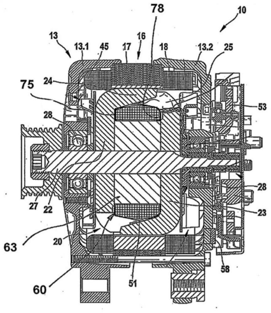
[0025] exist figure 1 A cross-section of an electric machine 10 , which in this embodiment is a generator or a three-phase alternator for a motor vehicle, is shown in . The electric machine 10 also has a two-part housing 13, which is formed from a first end shield 13.1 and a second end shield 13.2. The end shield 13.1 and the end shield 13.2 are accommodated in a so-called stator 16, which on the one hand consists of a substantially annular stator core 17 and in its radially inwardly directed, axial Stator windings 18 are embedded in ground-extending grooves.

[0026] The annular stator 16 surrounds, with its radially inwardly directed slotted surface, a rotor 20 , which is a claw-pole rotor. The rotor 20 also includes two claw-shaped pole plates 22 and 23, on the outer circumference of which claw-shaped pole pins 24 and 25 extending in the axial direction are respectively arranged. The two claw pole plates 22 and 23 are arranged in the rotor 20 such that their claw pole pi...


PUM


Abstract

The invention relates to a coil holder (101) for receiving a field winding of a rotor (20) of a motor. The coil holder comprises a cylindrical core element (150) for receiving the field winding and two limiting elements (75, 78) arranged on an axial edge of the core element (150), each of the two limiting elements (75, 78) is designed as an annular disk, and is provided with a plurality of wing-shaped elements (751, 781) which radially extend outwards from the disk, the coil carrier (101) has, for each limiting element (75, 78), at least one first recess (754, 784), which extends in the limiting element (75, 78) and in the core element (150), and a plurality of wing-shaped elements (751, 781) which project radially outward from the disk. The invention further relates to the motor comprising the coil holder.

Description

technical field [0001] The invention relates to a coil carrier for receiving a field winding of a rotor and to an electric machine with such a coil carrier. Background technique [0002] Known electric machines can be operated as generators and / or motors. Such electric machines usually have a rotor and a stator. The rotor can have two claw-shaped pole plates, on whose outer circumference claw-shaped pole pins are arranged. Such an electric machine is shown, for example, in document DE 10 2008 002 615 A1. This document also shows a coil carrier for accommodating the field winding of a rotor, said coil carrier having a cylindrical shell-shaped core element for accommodating the field winding and two axial edges arranged on the core element The upper limiting elements, wherein the two limiting elements are respectively configured as disks having an annular shape, and the disks have a plurality of wing-shaped elements protruding radially outward from the disks. [0003] In s...

Claims


Application Information

Patent Timeline
IPC IPC(8): H02K3/52
CPCH02K3/528H02K2203/12
Inventor 曾宪波
Owner SEG AUTOMOTIVE GERMANY GMBH
Why Eureka
Try Eureka