
Dust-dirt separation device and dust collector

A technology for separating devices and dust. It is applied in the installation of vacuum cleaners, suction filters, and electrical equipment. It can solve problems such as easy damage, and achieve the effect of improving user experience and reducing noise.

Pending Publication Date: 2021-04-16
GREE ELECTRIC APPLIANCES INC
View PDF0 Cites 0 Cited by
  • Summary
  • Abstract
  • Description
  • Claims
  • Application Information

AI Technical Summary

Problems solved by technology

[0007] Therefore, the technical problem to be solved by the present invention is to overcome the defect that the dirt separator in the prior art is prone to damage after being impacted by the air flow carrying large mass particles

Method used


Image

  • Dust-dirt separation device and dust collector
  • Dust-dirt separation device and dust collector
  • Dust-dirt separation device and dust collector

Examples


Embodiment

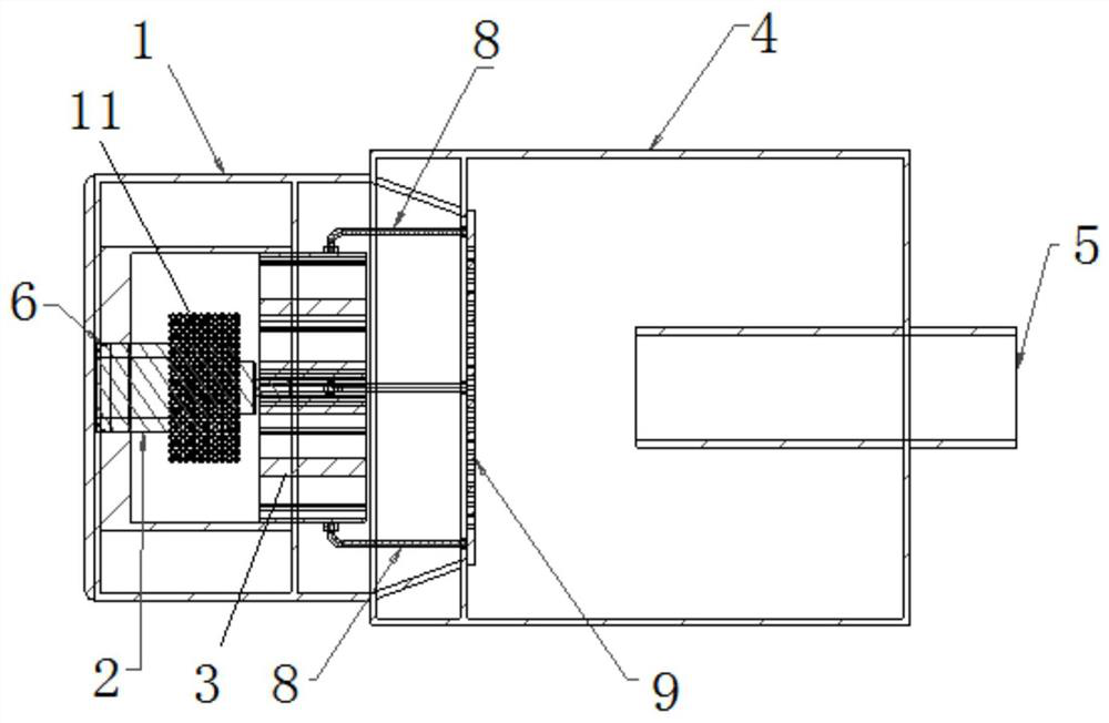
[0044] This embodiment provides a dust and dirt separation device, such as Figure 1-Figure 5 shown, including:

[0045] The main body 1 is provided with a vacuum motor inside; specifically, the main body 1 itself is provided with a cylindrical structure, and a cavity is provided inside the main body 1;

[0046] The wind wheel 3 is detachably arranged on the vacuum motor 2;

[0047] Specifically, by setting the wind wheel 3, the outside air can be sucked into the main body 1, and the air will carry dust, so as to facilitate the subsequent operation of separating the dust from the air.

[0048] The dust collecting chamber 4 is detachably arranged on the main body 1, and the dust collecting chamber 4 is provided with an opening 41, the main body 1 is connected with the dust collecting chamber 4 through the opening 41, the An air inlet 5 is arranged on the dust collecting chamber 4;

[0049] like figure 2 and image 3 As shown, an opening 41 is provided on the left side of ...

Embodiment 2

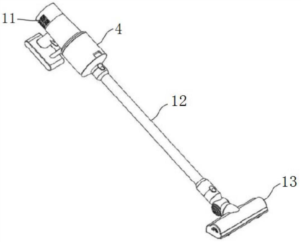
[0070] This embodiment provides a vacuum cleaner, such as figure 1 shown, including:

Embodiment 1

[0071] The dust separation device provided in embodiment 1;

[0072] Dust suction pipe 12, one end of which is connected to the air inlet 5 of the dust separation device;

[0073] The vacuum cleaner head 13 is connected to the other end of the dust suction pipe 12 . The vacuum cleaner head 13 itself will be in contact with the positions that need to be cleaned such as the ground, sofas, and corners. When the dust separation device starts to generate negative pressure, the negative pressure will suck the dust into the dust separation device through the dust suction pipe 12 through the vacuum cleaner head 13, thereby realizing the storage of the dust itself.

[0074] In this example, if figure 1 As shown, a handle can be directly provided on the dust separation device to form a hand-held vacuum cleaner. When the dust collection operation is required, the user can directly hold the handle to realize the dust collection operation.

[0075] As a modification, the dust and dirt s...


PUM


Abstract

The invention provides a dust-dirt separation device and a dust collector. The device comprises a main body which is internally provided with a vacuum motor; a wind wheel, which is detachably arranged on the vacuum motor; a dust collection cavity, which is detachably arranged on the main body, wherein an air inlet is formed in the dust collection cavity; and a vacuum motor mounting part, which is arranged in the main body. The vacuum motor is arranged on the vacuum motor mounting part. Air carrying dust enters the dust collection cavity through the air inlet, after the dust makes contact with a filter screen, the dust can be attached to the filter screen firstly, and at the moment, the filter screen is possibly blocked by the dust. However, due to the fact that the filter screen vibrates under the action of the vacuum motor, dust and dirt are separated from the filter screen after being vibrated by the filter screen, and then filter holes in the filter screen can be prevented from being blocked by dust and dirt particles.

Description

technical field [0001] The invention relates to the technical field of vacuum cleaners, in particular to a dust and dirt separation device and a vacuum cleaner. Background technique [0002] Vacuum cleaners are very common electrical appliances on the market. By installing a vacuum motor in the vacuum cleaner, the dusty air is sucked into the vacuum cleaner, after separation, the dust remains in the vacuum cleaner, and the filtered clean air is discharged to the outside. [0003] In the prior art, in order to realize the separation operation of dust and dirt, a bag separator or a cyclone separator is usually arranged inside the vacuum cleaner. [0004] For the bag separator, the main structure of the bag separator is a dust bag with filtering ability installed inside the vacuum cleaner. Dust. However, after using for a period of time, the small holes on the dust bag will be quickly blocked by dirt, resulting in a decrease in the suction of the vacuum cleaner; after the du...

Claims


Application Information

Patent Timeline
Patent Type & Authority Applications(China)
IPC IPC(8): A47L5/22A47L9/00A47L9/10A47L9/12A47L9/28
Inventor 张强弓
Owner GREE ELECTRIC APPLIANCES INC
Learn More