Hydraulic oil cylinder barrel and piston rod assembling device

A technology of hydraulic cylinder and assembly device, which is applied in metal processing, metal processing equipment, manufacturing tools, etc., can solve the problems of insufficient assembly accuracy, time-consuming and labor-intensive, and low concentration efficiency, and achieve the effect of saving manpower

Inactive Publication Date: 2021-04-16
娄底鼎力液压科技有限公司
View PDF0 Cites 0 Cited by
  • Summary
  • Abstract
  • Description
  • Claims
  • Application Information

AI Technical Summary

Problems solved by technology

[0004] The main purpose of the present invention is to provide a hydraulic cylinder barrel and piston rod assembly device, which can effectively solve the problems in the background technology that the structure is relatively complex, the concentration efficiency is low, the assembly accuracy is not high enough, and time-consuming and labor-intensive

Method used


Image

  • Hydraulic oil cylinder barrel and piston rod assembling device
  • Hydraulic oil cylinder barrel and piston rod assembling device
  • Hydraulic oil cylinder barrel and piston rod assembling device

Examples


Embodiment 1

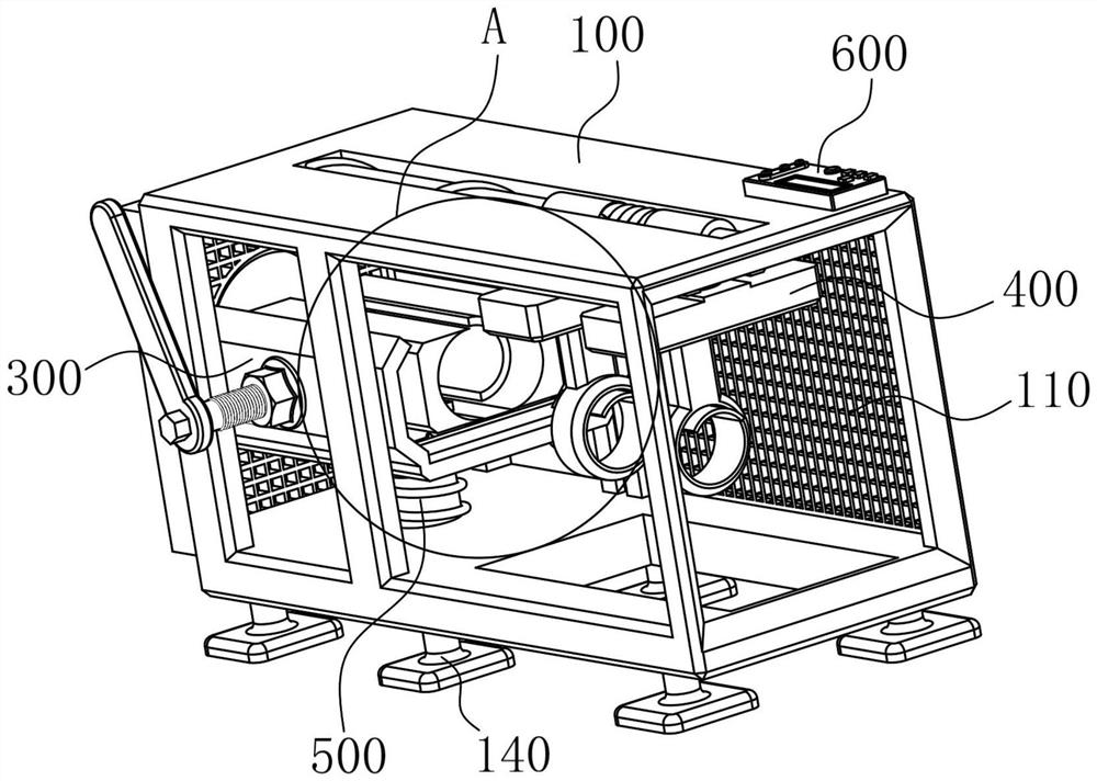
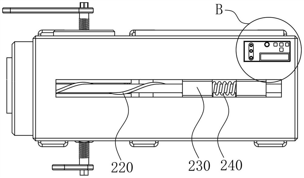
[0034] refer to figure 1 —8. The present invention is an assembly device for a hydraulic cylinder and a piston rod, including a main frame 100, a transmission device 200, a fastening device 300, a guiding and positioning device 400, a lifting device 500, and a console 600. The main frame 100 includes a main frame Skeleton body, grid plate 110, oil cylinder fixing plate 120 and fastening shaft partition 130, one end of grid plate 110 is connected with one surface of main frame body, one end of oil cylinder fixing plate 120 is connected with one surface of main frame body, fastening shaft spacer One end of the plate 130 is connected to one surface of the main frame body. The transmission device 200 includes a drive shaft 210, a transmission line 220, a first drive 230 and a second drive 250. The upper surface of the main frame body is provided with a rectangular through hole, and the drive shaft 210 is connected to the rectangular through hole. through-hole connection, the first...

Embodiment 2

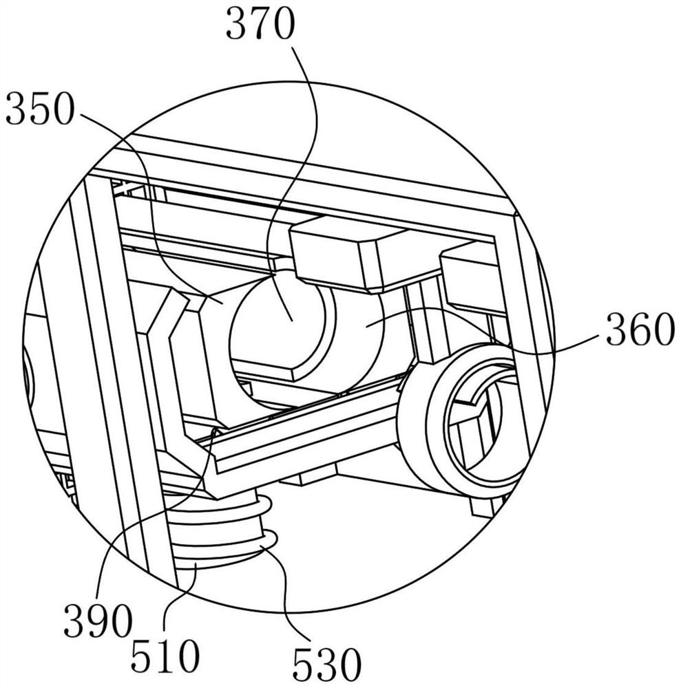
[0043] When the personnel is in use, place the cylinder on the placement plate 540, and tighten the first fastening frame 350 and the The second fastening frame 360, the piston rod is placed in the guide 410, the guide rod 430 and the connecting column 460 are matched together to adjust the position of the piston rod, and by observing the display screen 630, press the button 620 to adjust the position of the rod body, and the main switch 640 The transmission process is adjusted under control, and finally the piston rod is inserted into the cylinder body through the transmission shaft 210 and the transmission line 220 to complete the assembly.


PUM


Abstract

The invention relates to the technical field of cylinder barrel and piston rod assembling, in particular to a hydraulic oil cylinder barrel and piston rod assembling device. The hydraulic oil cylinder barrel and piston rod assembling device comprises a main framework, a transmission device, a fastening device, a guiding and positioning device, a lifting device and a control console. The main framework comprise a main framework body. The guiding and positioning device comprises guiders, guiding shafts, guiding rods, rod body fixing sleeves and connecting columns, the connecting columns mainly play a role in connection, one end of each guider is connected with the lower surface of the corresponding connecting column respectively, the guiders play a role in connecting the guiding shafts, and a rectangular mounting groove is formed in one surface of each guider. The guiding shafts are connected with the rectangular mounting grooves respectively and mainly connected with the guiders, the guiding rods are in sliding fit with the guiding shafts respectively, and one end of each rod body fixing sleeve is welded to the lower surface of the corresponding guiding rod respectively. The positions of an oil cylinder barrel and a piston rod are controlled through the fastening device and the guiding and positioning device, and the purpose of accurate positioning during assembling is achieved.

Description

technical field [0001] The invention relates to the technical field of assembling a cylinder barrel and a piston rod, in particular to an assembling device for a cylinder barrel and a piston rod of a hydraulic oil cylinder. Background technique [0002] The hydraulic cylinder is a hydraulic actuator that converts hydraulic energy into linear reciprocating motion and mechanical energy. This structure is simple and has high reliability. When using this structure to realize reciprocating motion, the deceleration device can be eliminated, and there is no transmission gap. , the movement is stable, so it is widely used in various mechanical hydraulic systems. The output force of the hydraulic cylinder is proportional to the effective area of ​​the piston and the pressure difference on both sides; the hydraulic cylinder is basically composed of a cylinder and a cylinder head, a piston and a piston rod, It is composed of sealing device, buffer device and exhaust device. The buffer ...

Claims


Application Information

Patent Timeline
Patent Type & Authority Applications(China)
IPC IPC(8): B23P19/00B23P19/02
Inventor 潘祥源
Owner 娄底鼎力液压科技有限公司
Why Eureka
Try Eureka