An anti-vibration cutting device for a self-insulating block cutting line

A self-insulating block and cutting device technology, applied in ceramic molding machines, manufacturing tools, etc., can solve the problems of inability to flexibly adjust the distance of the wire rope, increase the cost, and the resistance of the wire rope to advance, and achieve the advantages of transmission efficiency and cutting effect. The effect of reducing cutting resistance and improving work efficiency

Active Publication Date: 2022-03-04
许昌五星实业有限责任公司
View PDF0 Cites 0 Cited by
  • Summary
  • Abstract
  • Description
  • Claims
  • Application Information

AI Technical Summary

Problems solved by technology

[0002] The existing cutting process of self-insulating blocks is usually to cut the steel wire rope directly along the direction of its travel after contacting the brick adobe. If the group of steel wire ropes are cut at the same time, the travel resistance will be greater, and because the brick has a large water content after foaming, it has not yet been finalized, and its texture is relatively brittle, and excessive pressure is very easy to cause cracks in the body of the self-insulating block At the same time, because the steel wire rope is relatively soft and bears a large pressure, it is easy to cause deformation, which leads to changes in the size of the small blocks cut out, different specifications, and a high scrap rate
[0003] In the existing cutting structure, the steel wire rope will vibrate during the cutting process, causing the cutting surface to be uneven, and the blocks after cutting cannot be used, which increases the cost; Flexible size adjustment requires multiple devices and increases production costs. These are all problems that need to be solved

Method used


Image

  • An anti-vibration cutting device for a self-insulating block cutting line
  • An anti-vibration cutting device for a self-insulating block cutting line
  • An anti-vibration cutting device for a self-insulating block cutting line

Examples


Embodiment Construction

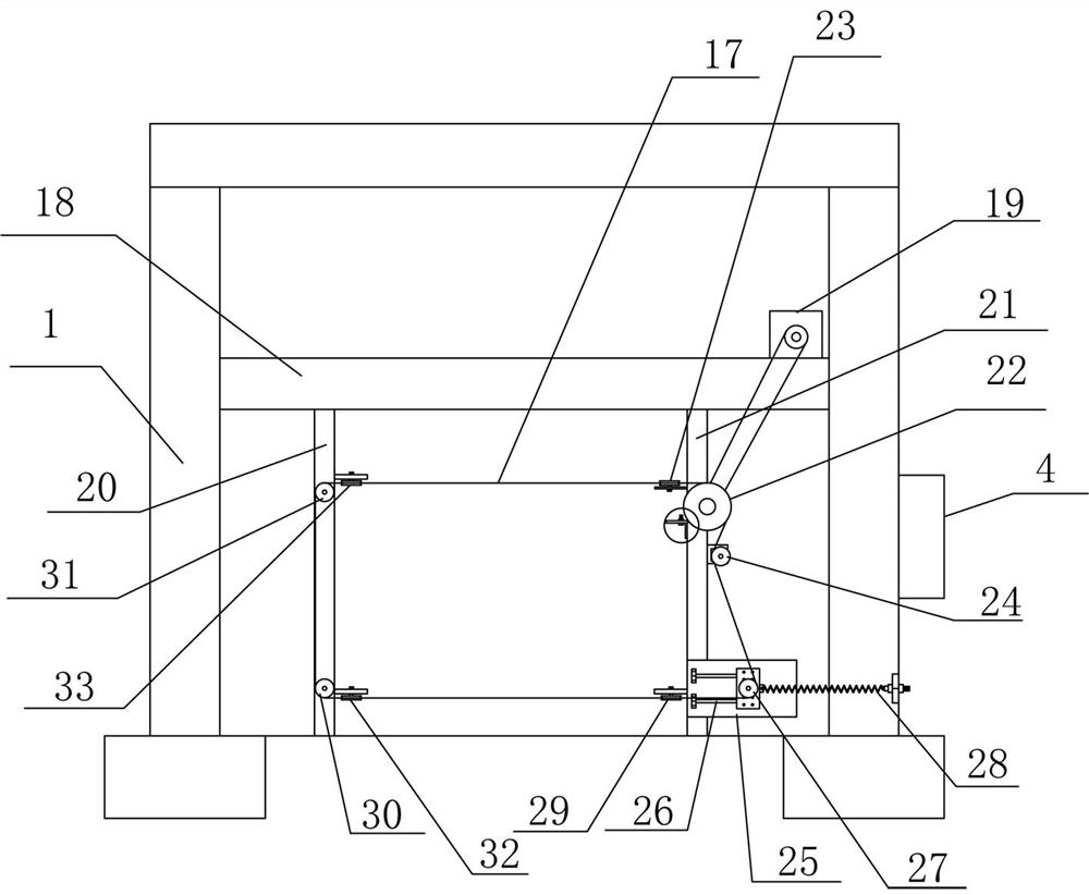
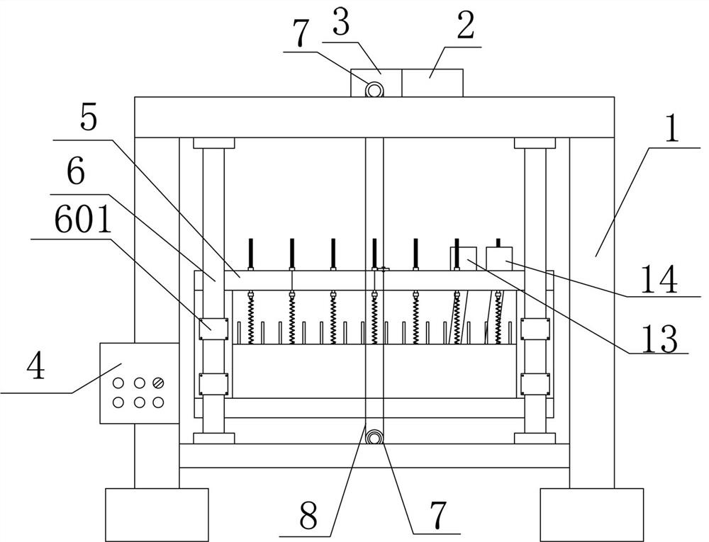
[0030] Such as Figure 1 to Figure 11 As shown, an anti-vibration cutting device for a self-insulating block cutting line includes a cutting machine frame 1, a lifting frame drive motor 2 and a double output shaft reducer 3 are installed on the top of the cutting machine frame 1, and the cutting machine A control cabinet 4 is installed on the frame 1, and the control cabinet 4 is electrically connected to the driving motor 2 of the lifting frame. The cutting machine frame 1 is provided with a top and bottom cutting structure and an equidistant vertical cutting structure. At the front end of the cutting machine frame 1, the equidistant vertical cutting structure is located inside the cutting machine frame 1, and both the top and bottom cutting structures and the equidistant vertical cutting structure are electrically connected to the control cabinet 4.

[0031] The top-cutting and bottom-cutting structure includes a mounting frame welded with the cutting machine frame 1 and a d...


PUM


Abstract

The invention relates to the field of self-insulation block production equipment, in particular to an anti-shake cutting device for a self-insulation block cutting line with no vibration and good cutting effect, including a cutting machine frame, which is equipped with a control cabinet and the top and bottom cut structure and equidistant vertical cut structure controlled by the control cabinet. The top and bottom cut structure is located at the front end of the cutting machine frame, and the equidistant vertical cut structure is located inside the cutting machine frame. The equidistant vertical cutting structure is wound with emery cutting wire. The emery cutting wire is wound on the winding wheel and rotates with the reel. A guide wheel is installed next to the reel to change the direction of the emery cutting wire and prevent the emery cutting wire from It falls off from the winding wheel and cuts during the rotation process to effectively reduce the cutting resistance. Multiple tensioning structures are set up to realize the tensioning of the transmission belt and cutting wire, which is beneficial to the transmission efficiency and cutting effect.

Description

technical field [0001] The invention relates to the field of self-insulation block production equipment, in particular to an anti-vibration cutting device for a self-insulation block cutting line without shaking and good cutting effect. Background technique [0002] The existing cutting process of self-insulating blocks is usually to directly cut the steel wire rope along the direction of its travel after contacting the brick adobe. If the group of steel wire ropes are cut at the same time, the travel resistance will be greater, and because the brick has a large water content after foaming, it has not yet been finalized, and its texture is relatively brittle. Excessive pressure is very easy to cause cracks in the body of the self-insulating block Even broken, at the same time because the steel wire rope is relatively soft, it also bears a large pressure, so it is easy to cause deformation, resulting in changes in the size of the small blocks cut out, different specifications...

Claims


Application Information

Patent Timeline
Patent Type & Authority Patents(China)
IPC IPC(8): B28B11/14
Inventor 李孝武李光耀郭延深杨建勋
Owner 许昌五星实业有限责任公司
Why Eureka
Try Eureka