
Mixer truck for building construction

A technology for building construction and mixer trucks, which is applied in construction, building structure, cement mixing devices, etc. It can solve the problems of poor mixing uniformity, low efficiency, and single operation mode, and achieve the effect of improving mixing accuracy

Active Publication Date: 2021-04-16
CHINA CONSTR SEVENTH ENG DIVISION CORP LTD
View PDF5 Cites 0 Cited by
  • Summary
  • Abstract
  • Description
  • Claims
  • Application Information

AI Technical Summary

Problems solved by technology

[0003] The existing mixer trucks are generally equipped with a mixing tank when in use, and then corresponding mixing tools are installed inside the tank body, so as to perform the function of mixing and feeding while moving, but the materials inside the existing mixer trucks are in the When stirring, only a simple stirring tool is used for stirring, the stirring uniformity is poor, the strength is small, and the operation method is single. When discharging, it needs to be discharged by manual operation, which is slow and inefficient.

Method used


Image

  • Mixer truck for building construction
  • Mixer truck for building construction
  • Mixer truck for building construction

Examples


Embodiment 1

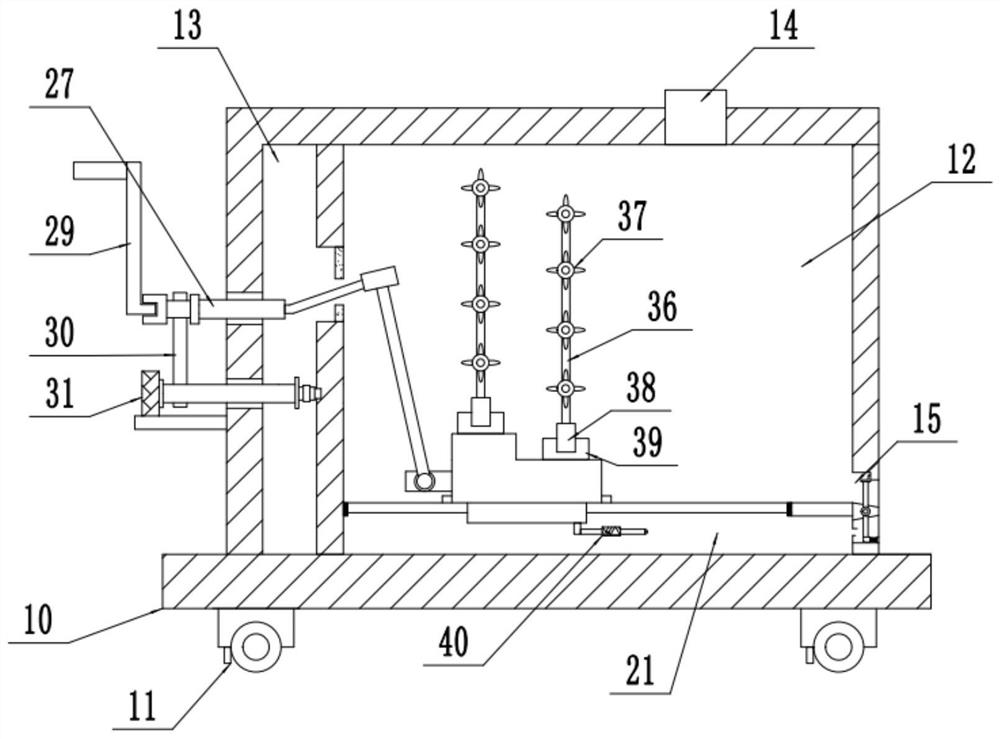
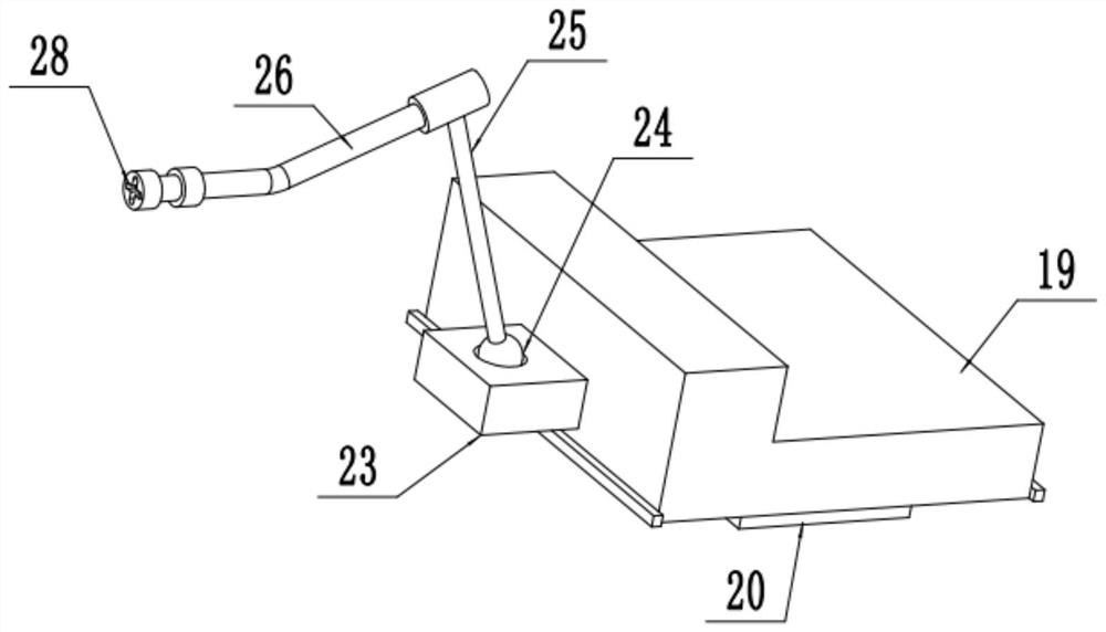
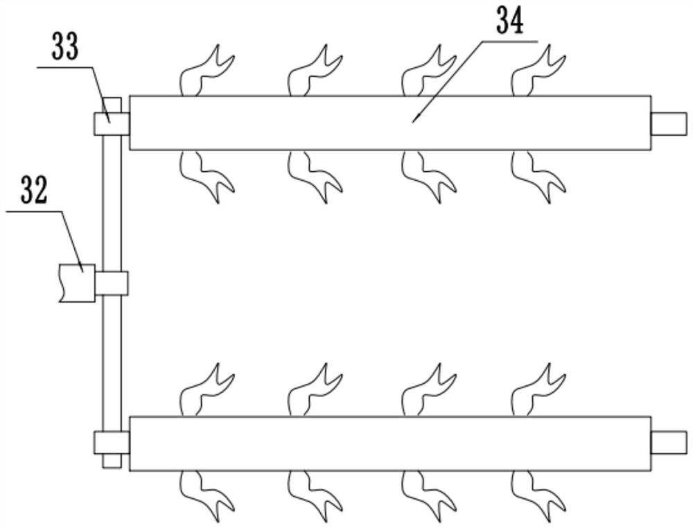
[0019] see Figure 1-3 , a building construction mixer truck, comprising a locomotive base 10, a moving wheel 11, a mixing chamber 12, a feed inlet 14, and a material outlet 15; the four corners of the bottom of the locomotive base 10 are rollingly connected with four groups of moving wheels 11, and the locomotive base The top of 10 is fixedly equipped with a group of stirring chambers 12, the top right side of the stirring chamber 12 is provided with a feed inlet 14, and the lower middle part of the right side wall is provided with a discharge port 15, and the inner left side of the stirring chamber 12 is passed through a vertical partition. The plate is provided with a set of power chambers 13 . The inner lower side of the locomotive base 10 is provided with a group of cavities 21 through a group of transverse partitions, and a transverse chute is provided in the middle of the transverse partition, and a group of sliders 20 are fixedly installed inside the chute. The top of...

Embodiment 2

[0022] refer to figure 1 , 4, on the basis of Embodiment 1, a set of vertical swing baffles 16 is rotatably connected to the inner middle of the discharge port 15, and a set of vertical swing baffles 16 is fixedly installed on the top of the swing baffle 16 to prevent the top of the swing baffle 16 from moving outwards. Limiting block 17, the right side of the bottom of the swing baffle 16 is elastically connected to the lower part of the inner right side wall of the discharge port 15 through a set of springs 18, and a set of left ends are arranged in the cavity 21 at the height of the middle part of the lower plate of the swing baffle 16. The electric telescopic rod 40 fixed on the bottom of the slider 20, the electric telescopic rod 40 moves left and right following the moving block 19, when it moves to the swing baffle 16, it can push the bottom of the swing baffle 16 to move to the right, and then swing the baffle The upper side of 16 moves outwards, and then opens the up...


PUM


Abstract

The invention relates to the technical field of building construction, and discloses a mixer truck for building construction. The mixer truck comprises a locomotive base, moving wheels, a mixing cavity, a feeding port and a discharging port. A set of power cavity is formed in the left side in the mixing cavity through a vertical partition plate, a transverse sliding groove is formed in the middle of a transverse partition plate, a set of sliding block is fixedly installed in the sliding groove, a set of moving block of an L-shaped structure is fixedly installed at the top of the sliding block, and a set of rectangular connecting block is fixedly installed in the middle of the left side wall of the moving block. A ball is connected in the upper side of the connecting block in a rolling manner, a set of first inclined connecting rod is rotatably connected to the top of the ball, a set of sleeve pipe is fixedly connected to the top end of the first connecting rod, and a set of second inclined connecting rod with the left end extending into the power cavity is sleeved in the sleeve pipe. A set of rotating through hole of a circular structure is formed in the joint of the middle of the second connecting rod and the vertical partition plate, and a set of rotating rod rotationally connected in the left side wall of the mixing cavity is fixedly installed at the left end of the second connecting rod.

Description

technical field [0001] The invention relates to the technical field of building construction, in particular to a building construction mixer truck. Background technique [0002] Building construction refers to the production activities in the implementation stage of engineering construction. It is the construction process of various buildings. It can also be said to be the process of turning various lines on the design drawings into physical objects at designated locations. A mixer truck is needed to mix the materials. [0003] The existing mixer trucks are generally equipped with a mixing tank when in use, and then corresponding mixing tools are installed inside the tank body, so as to perform the function of mixing and feeding while moving, but the materials inside the existing mixer trucks are in the When stirring, only a simple stirring tool is used for stirring, the stirring uniformity is poor, the strength is small, and the operation method is single. When discharging...

Claims


Application Information

Patent Timeline
IPC IPC(8): B28C5/14B28C5/48B28C5/44B28C5/08B28C7/16E04G21/02
Inventor 王作亮杨澎坡杨坤牛学亮李万山
Owner CHINA CONSTR SEVENTH ENG DIVISION CORP LTD
Learn More