Concrete making and painting all-in-one machine

An all-in-one machine and concrete technology, which is applied to clay preparation devices, construction material processing, and sales of raw material supply devices, etc., can solve the problems of increased operating costs, time-consuming, laborious, and large volume, and achieve improved mixing accuracy, reduced costs, and The effect of controlling the size of the device

Active Publication Date: 2021-11-23
台州豪鑫汽车部件有限公司
View PDF0 Cites 0 Cited by
  • Summary
  • Abstract
  • Description
  • Claims
  • Application Information

AI Technical Summary

Problems solved by technology

[0004] The main purpose of the present invention is to overcome the deficiencies of the prior art, and provide a concrete making and painting all-in-one machine to solve the problem of transferring to the painting equipment after the concrete is made, which is time-consuming and laborious, and increases the operating cost. Stirring, the volume of the equipment is large, how to realize the assembly of the two machines while ensuring the minimization of the volume is a problem that needs to be improved in the existing technology

Method used


Image

  • Concrete making and painting all-in-one machine
  • Concrete making and painting all-in-one machine
  • Concrete making and painting all-in-one machine

Examples


Embodiment 1

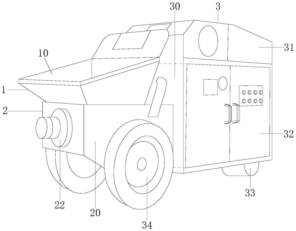
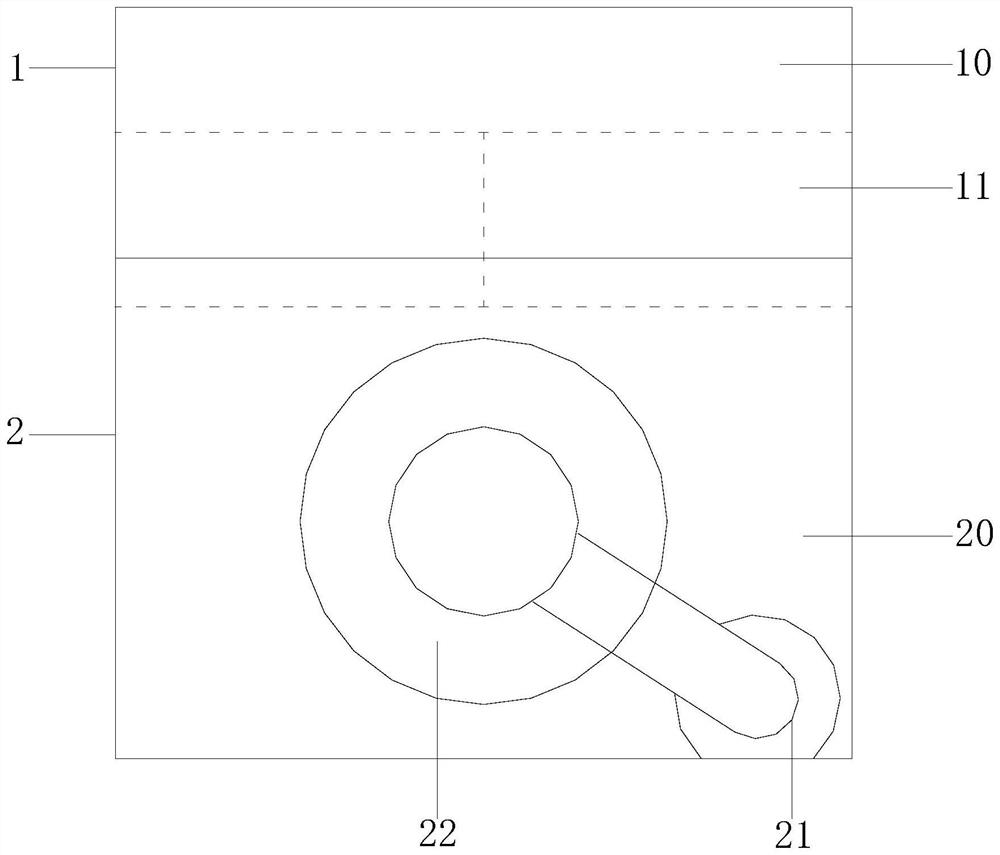
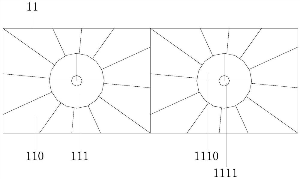
[0025] Example 1 see Figure 1-3 , the present invention provides a technical solution for a concrete making and painting all-in-one machine: its structure includes a feed hopper 1, a painting box structure 2, and a main transmission control box 3. Installed and connected, the feed hopper 1 is located above the smear box structure 2, the feed hopper 1 is composed of a hopper body 10 and a feed port 11, the hopper body 10 is equipped with a feed port 11, and the smear box Structure 2 includes a smear box frame 20, a feeder 21, and a smear device 22, the smear box frame 20 is connected to the smear device 22, the feeder 21 is installed on the smear device 22, and the feed port 11 includes Concave frame 110, screw feed port 111, the feed port 11 is a concave structure, the material slides along the concave frame 110 to the screw feed port 111, and then enters the internal stirring device 30 in a spiral manner, and the materials are classified into Once entering, the feed is orde...

Embodiment 2

[0027] Example 2 see Figure 4-6 , the present invention provides a technical solution for a concrete making and painting all-in-one machine: the internal mixing device 30 includes an upper assembly frame 300, a lower assembly frame 301, an assembly round button 302, and a stirring device 303. The upper assembly frame 300 and the lower assembly The assembly frame 301 is assembled and connected, the upper assembly frame 300, the lower assembly frame 301 are installed and connected with the assembly round button 302, the stirring device 303 is installed on the upper assembly frame 300, the lower assembly frame 301, and the stirring device 303 includes a stirring Inner cylinder 3030, stirring shaft fan 3031, automatic material opening 3032, the stirring inner cylinder 3030 is installed and connected with the stirring shaft fan 3031, the stirring shaft fan 3031 is used for stirring materials, and is obliquely installed on the stirring inner cylinder 3030, Stirring inner cylinder 3...


PUM


Abstract

The invention discloses an integrated machine for making and coating concrete. Its structure includes a feeding hopper, a coating box structure, and a main transmission control box. Above, the feeding hopper is composed of a hopper body and a feeding port. The hopper body is equipped with a feeding port. The coating box structure includes a coating box frame, a feeder, and a coating device. The coating box frame is installed and connected to the coating device. The feeder Installed on the smearing device, the feeding port includes a concave frame and a screw feeding port. The concave frame is assembled and connected with the screw feeding port. The screw feeding port includes a spiral panel and a plate-mounted shaft. The spiral panel and the plate-mounted shaft are installed and connected. In the present invention, the material is fed from the hopper body to the internal stirring device for stirring, and then discharged from the coating box structure for coating. The production and coating are integrated, saving time and effort and reducing costs. The mixing drum is installed obliquely, which not only ensures uniform stirring , and also reasonably control the size of the equipment.

Description

technical field [0001] The invention relates to the field of construction equipment, in particular to an integrated concrete making and painting machine. Background technique [0002] To make concrete, you need to prepare yellow sand, cement, and stones. After adjusting the ratio, mix the yellow sand and cement evenly. After completion, it is sent to the designated equipment for smearing. [0003] In the prior art, the concrete is transferred to the smearing equipment after the completion of the production, which is time-consuming and laborious, and increases the operating cost. The concrete is mixed in a zigzag shape when making the mixing, and the volume of the equipment is relatively large. How to realize the assembly of the two machines while ensuring the minimum volume There is room for technical improvement. Contents of the invention [0004] The main purpose of the present invention is to overcome the deficiencies of the prior art, and provide a concrete making an...

Claims


Application Information

Patent Timeline
Patent Type & Authority Patents(China)
IPC IPC(8): B28C5/12B28C7/06E04G21/02
CPCB28C5/0806B28C5/0818B28C5/12B28C7/067E04G21/02
Inventor 李远铭
Owner 台州豪鑫汽车部件有限公司
Why Eureka
Try Eureka