
Angle-adjustable supporting equipment for conveying pipes and working method of angle-adjustable supporting equipment

It is a support equipment and adjustable technology, which is applied in the direction of conveyors, conveyor objects, mechanical conveyors, etc. It can solve the problems of affecting the transfer efficiency, inconvenient loading and unloading, and unstable pipeline status, so as to improve the transfer efficiency, facilitate cooperative operation, Good clamping effect

Inactive Publication Date: 2021-04-16
马鞍山天哲环保科技有限公司
View PDF0 Cites 0 Cited by
  • Summary
  • Abstract
  • Description
  • Claims
  • Application Information

AI Technical Summary

Problems solved by technology

[0004] The purpose of the present invention is to provide an angle-adjustable supporting device for transporting pipes and its working method, which solves the problem of being bound and fixed by chains. When fixing, the contact point between the chains and the pipeline is small. When fixing, the state of the pipeline is unstable. It is easy to break the chain, which is not convenient for transfer and transportation. During transfer, because the transfer frame is a fixed structure, it is difficult to adjust the angle of the transfer frame during transfer, which is inconvenient and loading and unloading, which affects the technical problems of transfer efficiency.

Method used


Image

  • Angle-adjustable supporting equipment for conveying pipes and working method of angle-adjustable supporting equipment
  • Angle-adjustable supporting equipment for conveying pipes and working method of angle-adjustable supporting equipment
  • Angle-adjustable supporting equipment for conveying pipes and working method of angle-adjustable supporting equipment

Examples


Embodiment approach

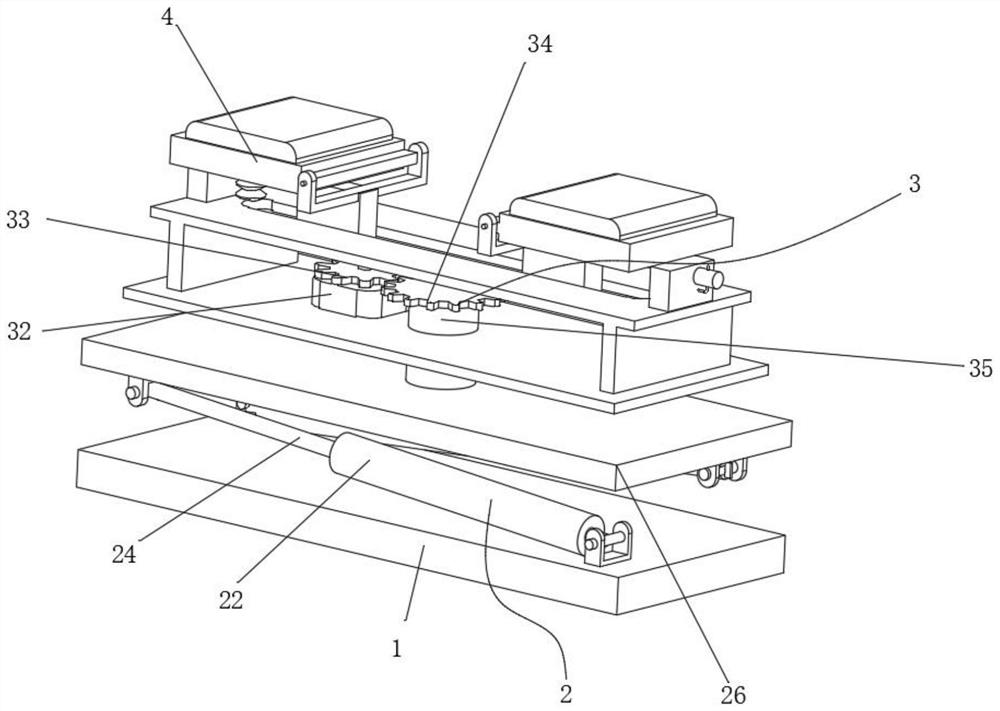
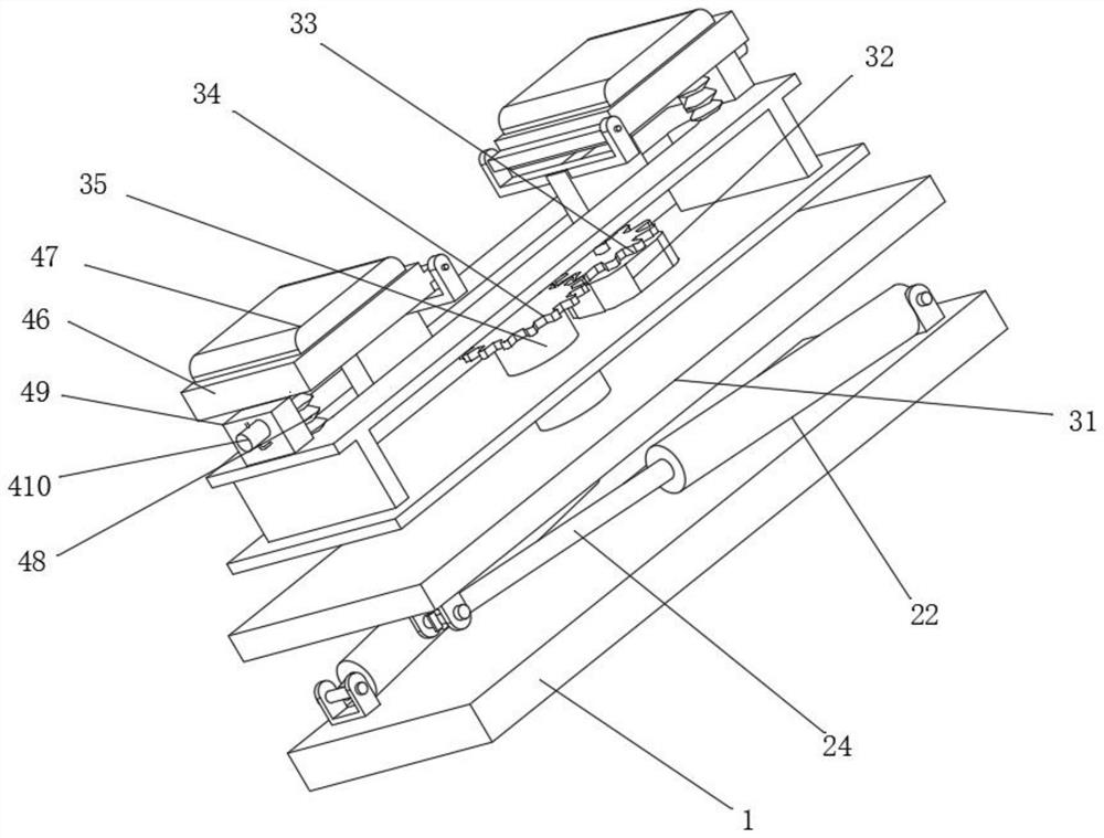
[0031]As an embodiment of the present invention, the support assembly 2 includes a mounting base 21, a hydraulic column 22, a slider 23, a hydraulic rod 24, a slide rail 25 and a support plate 26, and the mounting base 21 is symmetrically installed on the top side of the base 1, and the installation The inside of the seat 21 is mounted on the hydraulic column 22 through hinged fit, the hydraulic rod 24 at the working end of the hydraulic column 22, the bottom side of the support plate 26 is symmetrically installed with a slide rail 25, and the slide block 23 is matched and snapped on the slide rail 25, and the hydraulic rod The top of 24 is hingedly installed on the bottom of slide block 23, and hydraulic column 22 and hydraulic rod 24 are intersected between support plate 26 and base 1, and a spirit level is installed on support plate 26. The horizontal ruler observes the inclination of the support plate 26. Through the operation of the hydraulic column 22 on one side, under t...


PUM


Abstract

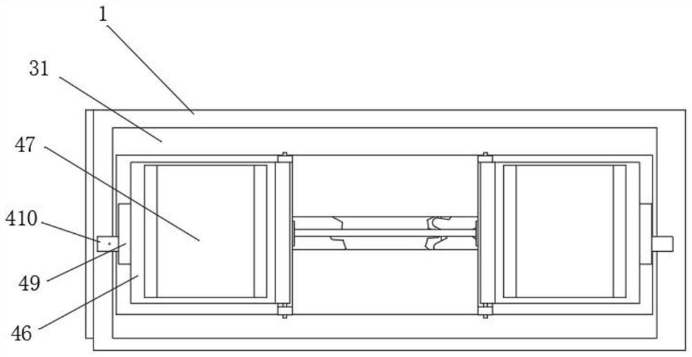
The invention discloses angle-adjustable supporting equipment for conveying pipes and a working method of the angle-adjustable supporting equipment. The angle-adjustable supporting equipment comprises a base, a supporting assembly, a rotating assembly and a calibration clamping assembly, wherein the supporting assembly is installed on the top side of the base in a matched mode, the rotating assembly is installed on the supporting assembly, the calibration clamping assembly is installed on the rotating assembly, through the supporting assembly, when supporting and transferring are conducted, through operation of a single-side hydraulic column, under cooperation of a hydraulic rod, a sliding block can be pushed to slide along a sliding rail, the hydraulic rod continues to extend, jacking of the side edge of a supporting plate can be achieved, the inclination degree of the supporting plate can be adjusted, during transferring, parallelism of the base can be guaranteed, transferring stability is guaranteed, by arranging the rotating assembly, a rotating motor works, a driving gear is driven to rotate, under the cooperation of a matching gear, a rotating plate can be reversely pushed to rotate around a rotating column, a rotating angle of a supporting frame can be changed, the pipes can be transferred in a matched mode, more convenient matching operation can be achieved, and the pipe transferring efficiency can be improved.

Description

technical field [0001] The invention relates to the technical field of pipe transfer, in particular to an angle-adjustable supporting device for pipe transfer and a working method thereof. Background technique [0002] Pipes are necessary materials for construction projects. Commonly used are water supply pipes, drainage pipes, gas pipes, heating pipes, wire conduits, rainwater pipes, etc. With the development of science and technology, the pipes used in home decoration have also experienced the development process of ordinary cast iron pipe → cement pipe → (reinforced concrete pipe, asbestos cement pipe) → ductile iron pipe, galvanized steel pipe → plastic pipe and aluminum-plastic composite pipe ; [0003] Due to the cylindrical structure of the pipe, the fluidity of the pipe is relatively large during transportation. When fixing the pipe, it is generally fixed by chain binding. When fixing, the contact point between the chain and the pipe is small. When fixing, the state...

Claims


Application Information

Patent Timeline
Patent Type & Authority Applications(China)
IPC IPC(8): B65G35/00B65G47/22
Inventor 沈玉鹏朱鹏
Owner 马鞍山天哲环保科技有限公司
Learn More