Moving object positioning method and device, electronic equipment and storage medium

A moving object and positioning method technology, applied in the field of image recognition, can solve the problems of waste of computing resources, large amount of calculation for image feature extraction, difficulty in ensuring real-time image recognition, etc., and achieve the effect of improving positioning efficiency and improving real-time detection

Pending Publication Date: 2021-04-16
LYNXI TECH CO LTD
View PDF6 Cites 10 Cited by
  • Summary
  • Abstract
  • Description
  • Claims
  • Application Information

AI Technical Summary

Problems solved by technology

[0004] However, in such an image recognition method, the extraction of image features requires a huge amount of calculations, and because most of the images taken by the camera components remain static, it often results in a waste of computing resources. At the same time, through image features, comparing objects in different images It is difficult to guarantee the real-time performance of image recognition, especially for high-speed moving objects, the positioning effect is poor

Method used


Image

  • Moving object positioning method and device, electronic equipment and storage medium
  • Moving object positioning method and device, electronic equipment and storage medium
  • Moving object positioning method and device, electronic equipment and storage medium

Examples


Embodiment 1

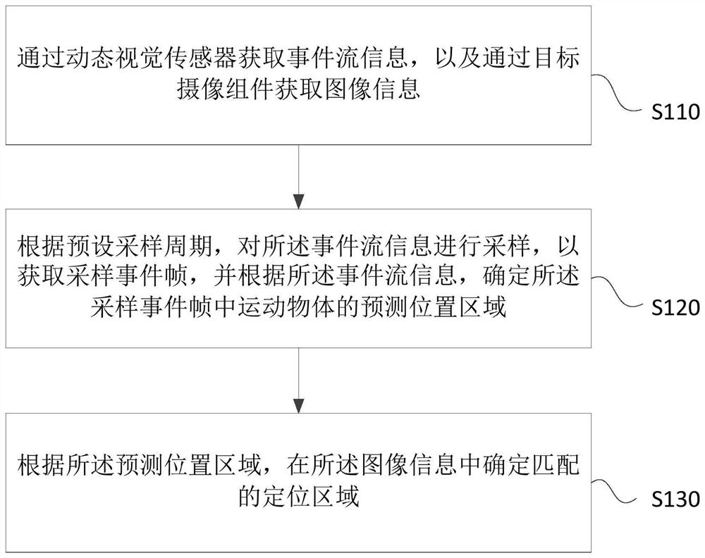
[0027] Figure 1A It is a flow chart of a method for locating a moving object provided by Embodiment 1 of the present invention. This embodiment is applicable to detecting whether there is a moving object in the image information captured by the target camera component. This method can be implemented by the moving object in the embodiment of the present invention The positioning device is implemented, the device can be implemented by software and / or hardware, and integrated in the electronic device, the method specifically includes the following steps:

[0028] S110. Acquire event flow information through a dynamic vision sensor, and acquire image information through a target camera component.

[0029] Dynamic Vision Sensor (DVS) is an image acquisition device that adopts a pixel asynchronous mechanism and is based on Address and Event Expression (AER); it differs from traditional technical solutions in that it is based on "frames" collected at a fixed frequency , and sequenti...

Embodiment 2

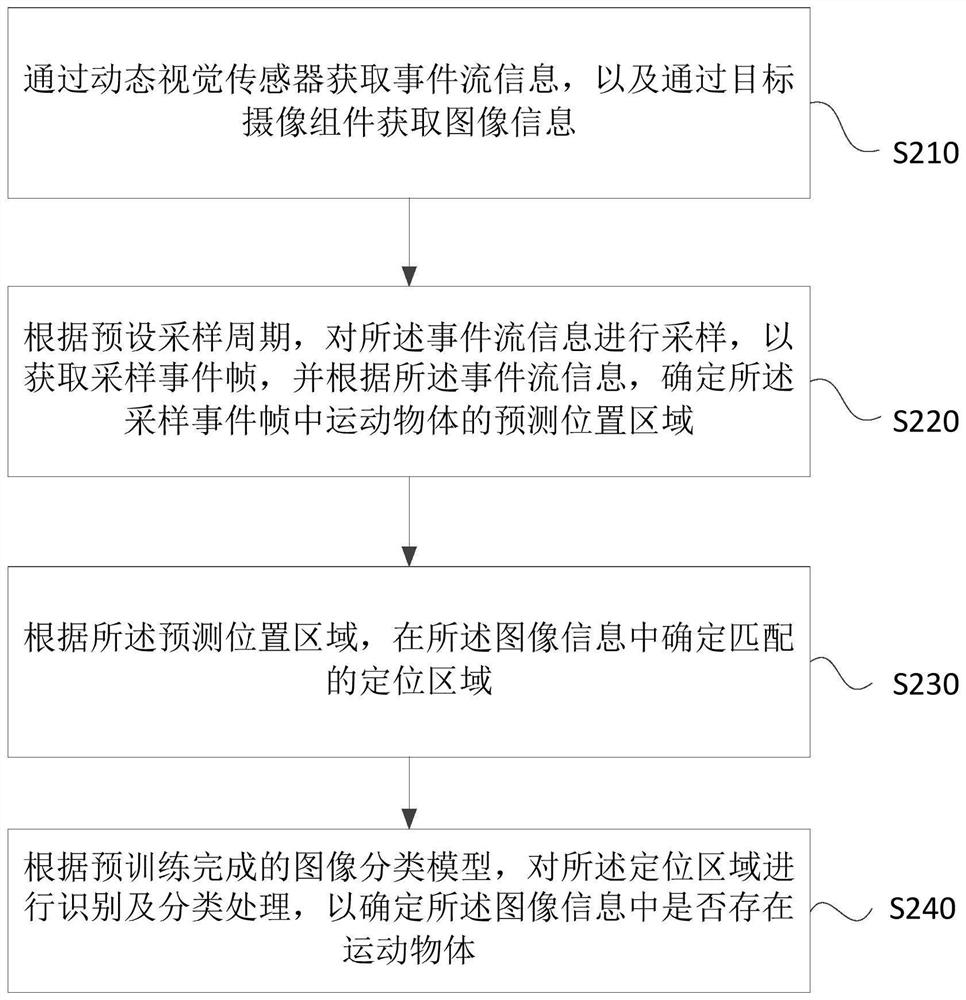
[0046] figure 2 It is a method for locating a moving object provided in Embodiment 2 of the present invention. The method is embodied on the basis of the above-mentioned technical solution. In the embodiment of the present invention, according to the pre-trained image classification model, the positioning The region is identified and classified to determine whether there is a moving object in the image information. The method specifically includes:

[0047] S210. Acquire event flow information through a dynamic vision sensor, and acquire image information through a target camera component.

[0048] S220. Sampling the event flow information according to a preset sampling period to obtain a sampled event frame, and determining a predicted position area of ​​a moving object in the sampled event frame according to the event flow information.

[0049] S230. Determine a matching positioning area in the image information according to the predicted location area.

[0050] S240. Per...

Embodiment 3

[0056] image 3It is a structural block diagram of a device for positioning a moving object provided in Embodiment 3 of the present invention, and the device specifically includes: an information acquisition module 310, a sampling execution module 320, and a classification execution module 330;

[0057] An information acquisition module 310, configured to acquire event flow information through a dynamic visual sensor, and acquire image information through a target camera assembly;

[0058] The sampling execution module 320 is configured to sample the event flow information according to a preset sampling period to obtain a sampled event frame, and determine the predicted position area of ​​the moving object in the sampled event frame according to the event flow information;

[0059] The classification execution module 330 is configured to determine a matching positioning area in the image information according to the predicted location area.

[0060] In the technical solution ...


PUM


Abstract

The embodiment of the invention discloses a moving object positioning method and device, electronic equipment and a storage medium. The method comprises the steps: acquiring event flow information through a dynamic vision sensor, and acquiring image information through a target camera shooting assembly; sampling the event flow information according to a preset sampling period to obtain a sampling event frame, and determining a prediction position area of a moving object in the sampling event frame according to the event flow information; and determining a matched positioning area in the image information according to the predicted position area. According to the technical scheme disclosed by the embodiment of the invention, the prediction position area of the moving object in the sampling event frame is determined after the event flow information is obtained through the dynamic vision sensor, and the matched positioning area is determined in the image information of the target camera component, so that the positioning efficiency of the moving object is improved; and particularly, the detection real-time performance of the high-speed moving object is improved.

Description

technical field [0001] Embodiments of the present invention relate to the technical field of image recognition, and in particular, to a positioning method, device, electronic equipment, and storage medium for a moving object. Background technique [0002] With the continuous advancement of science and technology, image recognition technology has developed rapidly and is widely used in various fields. Among them, the positioning of high-speed moving objects in images has become an important branch of image recognition technology. [0003] In the prior art, feature extraction is usually performed directly on the global image for the video image acquired by the camera component, and a moving object is located in the image according to the extracted image feature. [0004] However, in such an image recognition method, the extraction of image features requires a huge amount of calculations, and because most of the images taken by the camera components remain static, it often resu...

Claims


Application Information

Patent Timeline
Patent Type & Authority Applications(China)
IPC IPC(8): G06T7/20G06T7/70G06K9/62
CPCG06T7/20G06T7/70G06F18/00
Inventor 马欣吴臻志
Owner LYNXI TECH CO LTD
Why Eureka
Try Eureka