Multi-sensor time synchronization method, device and system, electronic device and medium

A multi-sensor, time synchronization technology, applied in the field of communication, can solve the problems of lack of multi-sensor high-precision time synchronization method, weak GPS signal, etc., and achieve good scalability and portability

Active Publication Date: 2021-04-16
ZHEJIANG LAB
15 Cites 8 Cited by

AI-Extracted Technical Summary

Problems solved by technology

[0004] The purpose of the embodiments of the present application is to provide a multi-sensor time synchronization method, device, system, electronic equipment, and medium to solve the scene of we...

Method used

[0039] Step S102, sending the pulse count value of the second pulse signal and the internal time stamp generati...

Abstract

The invention discloses a multi-sensor time synchronization method, device and system, an electronic device and a medium, and the method comprises the steps: receiving initial timestamp time service transmitted by an upper computer, starting an internal timer, and generating a first trigger pulse signal and a second trigger pulse signal; sending the timestamp for generating the second trigger pulse signal and a pulse count value to the upper computer for realizing matching alignment with sensor data; simulating a GPS receiver function, generating a pulse per second synchronization signal and a time message, and sending the pulse per second synchronization signal and the time message to the first sensor and the second sensor to enable the sensors and the time main control equipment to realize internal timing synchronization; and respectively sending the first trigger pulse signal and the second trigger pulse signal to a second sensor and a third sensor for triggering the two types of sensors to perform data acquisition and sending the acquired data to an upper computer. Therefore, multi-sensor data acquisition time synchronization is realized, and the problem of multi-sensor time synchronization in a scene of weak GPS or no GPS signal and no real time service is solved.

Application Domain

Synchronisation arrangementParticular environment based services +1

Technology Topic

Pulse synchronizationTimer +11

Image

  • Multi-sensor time synchronization method, device and system, electronic device and medium
  • Multi-sensor time synchronization method, device and system, electronic device and medium
  • Multi-sensor time synchronization method, device and system, electronic device and medium

Examples

  • Experimental program(1)

Example Embodiment

[0029] Exemplary embodiments will be described in detail herein, examples of which are illustrated in the accompanying drawings. Where the following description refers to the drawings, the same numerals in different drawings refer to the same or similar elements unless otherwise indicated. The implementations described in the illustrative examples below are not intended to represent all implementations consistent with this application. Rather, they are merely examples of apparatus and methods consistent with some aspects of the present application as recited in the appended claims.
[0030] The terminology used in this application is for the purpose of describing particular embodiments only and is not intended to limit the application. As used in this application and the appended claims, the singular forms "a," "the," and "the" are intended to include the plural forms as well, unless the context clearly dictates otherwise. It will also be understood that the term "and/or" as used herein refers to and includes any and all possible combinations of one or more of the associated listed items.
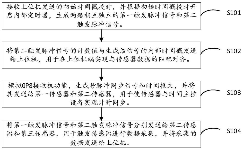
[0031] figure 1 is a flow chart of a multi-sensor time synchronization method according to an exemplary embodiment, such as figure 1 As shown, the method is applied to a time master control device and may include the following steps:
[0032] Step S101, receiving the initial time stamp timing sent by the host computer, starting the internal timer, performing time stamp accumulation, and generating two independent trigger pulse signals;
[0033] In this embodiment, the host computer may be various types of PC hosts, or may be a hardware platform based on embedded chips. In this embodiment, an industrial control host based on a Linux system is used as an example. The time master control device may be an embedded platform such as MCU, DSP, or FPGA. In this embodiment, an STM32 single-chip microcomputer system is used as an example. STM32 series MCU is based on ARM core, mounted with 8MHz high-precision clock crystal oscillator, and has abundant internal timer resources, which can provide clock for MCU system and generate trigger pulse signals of various frequencies.
[0034] This step contains the following sub-steps:
[0035] S1011, through the hardware interface between the host computer and the time master control device, receive the initial time stamp timing sent by the host computer; , the interface communication driver is designed to receive the initial time stamp generated by the host computer, wherein the initial time stamp is obtained by the host computer reading the internal time of the computer system. In this embodiment, the RS232 serial interface is used for communication between the time master control device and the upper computer, and the maximum baud rate can reach 921600bps. The time master control device receives the time service from the upper computer through the serial port, and obtains the microsecond time of the timing time. The stamp is stored in the register as the start time of the time synchronization system.
[0036] S1012, a timer is started to accumulate time, and an internal time stamp is updated. Specifically, after receiving the initial time stamp sent by the host computer, the internal timer T1 for accumulative timing is started. The frequency of the internal timer T1 is based on the fixed frequency high-precision crystal oscillator mounted in the hardware system. obtained by multiplying the frequency. By configuring the timer T1, it overflows and counts again after accumulating for a period of time t0, and accumulates t0 to the received initial timestamp, so as to obtain the continuously updated internal timestamp. For sensors without an internal clock, the internal timestamp generated by the time master device can be regarded as the precise time when the sensor collects data, and is used to synchronize the time of other sensors in the system.
[0037]S1013, configure the internal timers T2 and T3 as PWM output mode, so that they can output two independent trigger pulse signals. In this embodiment, according to the frequency requirements of the data collected by the second sensor and the third sensor, a first trigger pulse signal with a frequency of f0 and a second trigger pulse signal with a frequency of f1 are generated, which are used for external triggering for these two types of sensors. Pattern acquisition data provides the required trigger signal. Since the time master device timer supports multiple PWM pulse outputs, and can configure the edge alignment of the trigger pulse, the edge deviation of the trigger pulse does not exceed 100ns. Therefore, multiple sensors can be triggered synchronously to achieve synchronous acquisition of multi-sensor data.
[0038] In the embodiment of the present application, the second sensor represents a sensor with an internal clock, which can be time-synchronized with the time master device according to the pulse-per-second synchronization signal, or can perform data collection in an external trigger mode according to the trigger pulse signal. An example of this type of sensor is an IMU; the third sensor means a sensor that does not support timing synchronization based on a second pulse signal, but supports triggering data collection based on a trigger pulse signal. This type of sensor takes a camera as an example.
[0039] Step S102, sending the pulse count value of the second pulse signal and the internal time stamp for generating the trigger signal to the host computer, so as to realize the matching and alignment with the sensor data at the host computer end.
[0040] This step contains the following sub-steps:
[0041] S1021, while generating the second trigger pulse signal with a frequency of f1, record the internal time stamp of each generation of the trigger pulse signal, and record the count value of the trigger pulse from 1;
[0042] S1022, through the RS232 serial communication interface with the upper computer, send the internal time stamp and the count value of the trigger pulse to the upper computer according to the frequency of f1. The internal time stamp and trigger pulse count value are used to match the data of the third sensor at the host computer end. The host computer obtains a set of data frame count values ​​from the third sensor, and by matching the two sets of counts, each frame of data of the third sensor can be matched with a set of time stamps corresponding to the time of data collection.
[0043] Step S103, simulating the function of the GPS receiver, generating a pulse-per-second synchronization signal and a timing message, and sending them to the first sensor and the second sensor.
[0044] Timing GPS receivers can use the high-precision time standards provided by GPS satellites for timing, and use GPS signals as time benchmarks to provide pulse signals and time messages in various interface forms for the time-served equipment. In this embodiment, for scenarios without GPS or weak GPS such as celestial environment and underground airtight environment, the time master control device is used to simulate the GPS receiver function, and the second pulse synchronization signal and time message are generated to realize the effect of simulating GPS timing synchronization. The synchronization accuracy can reach the millisecond level.
[0045] In the embodiment of the present application, the first sensor refers to a sensor that supports the GPS function, and can perform time synchronization according to GPS timing. In this embodiment, such a sensor is a LiDAR (Light Detection And Ranging, LIDAR) as an example; The sensor does not support the GPS function, but can synchronize with the time master device according to the pulse-per-second synchronization signal, taking the IMU as an example.
[0046] This step contains the following sub-steps:
[0047] S1031 , configure the internal timer T4 as a PWM output mode, and after receiving the initial time stamp sent by the host computer, start the timer T4 to generate a second pulse synchronization signal.
[0048] S1032, simulates the GPS receiver function, generates and sends a time message at a frequency consistent with the second pulse synchronization signal, and the complete message includes geographic information such as latitude, longitude, altitude, and time information such as hour, minute, and second. In terms of time sequence, the time interval between the time message and the next second pulse synchronization signal needs to be greater than 300ms. In the embodiment of the present application, the time master control device updates the time, minutes and seconds information in the message every time it sends a time message based on the continuously accumulated internal time stamp, and sends it to the lidar through the universal asynchronous transceiver transmission interface. Lidar provides timing.
[0049] S1033, send the second pulse synchronization signal and the time message to the lidar. Specifically, the lidar has a whole-second timer and a microsecond timer. After receiving the second pulse synchronization signal, the internal microsecond timer is set to zero at the rising edge of the pulse. When a time packet arrives, the system extracts the time information in the packet and updates the internal time of the whole-second timer, so as to achieve microsecond-level time synchronization between the lidar and the time master device. At the same time, the phase-locking function of the lidar is configured, and by setting the starting phase of the laser transmitter rotation, the laser transmitter can be accurately rotated to the center of the camera's viewing angle range when the camera is exposed, so as to obtain time- and space-synchronized lidar points Cloud data and camera image data.
[0050] S1034: Send the pulse-per-second synchronization signal to the IMU. Specifically, in order to make the IMU and the time master device have a consistent time reference, and to obtain an accurate time stamp of IMU data collection, . When the time master device receives the initial time stamp of the host computer, the host computer sends the initial time stamp to the IMU at the same time. Since the IMU has a timer inside, it can independently configure and generate an internal time stamp. After the IMU receives the initial time stamp of the upper computer, it can have the same initial time as the time master device and start the accumulation of internal time stamps at the same time. After the time master device generates the second pulse synchronization signal, one channel is sent to the lidar, and the other channel is sent to the IMU synchronously, which is used to synchronize the timing of the internal timer of the IMU. The IMU is configured to work in a time synchronization (ClockSync) working mode, and after the IMU receives the second pulse synchronization pulse signal, it adjusts the internal clock autonomously to achieve internal timing synchronization with the time master device. So far, the IMU and the time master device have the same initial time stamp and synchronous accumulation frequency. In the subsequent data collection of the IMU, the internal time stamp of the sensor can be used, and the time stamp can be compared with other sensors that use the internal time stamp of the time master device. Synchronize.
[0051] Step S104: Send the generated first trigger pulse signal and second trigger pulse signal to the second sensor and the third sensor respectively, so that the second and third sensors collect data according to the frequency of the trigger pulse signal. Wherein, according to the method of step S103, the second sensor can generate an internal time stamp synchronized with the timing of the time master device, package the data triggered to collect with the corresponding internal time stamp and send it to the host computer; the third sensor will trigger the collected data The data is directly sent to the host computer, and is matched and aligned with the time stamp of the time master device on the host computer side.
[0052] In the embodiment of the present application, the sensor that receives the trigger pulse signal includes a second sensor and a third sensor. The second sensor is an IMU, and the third sensor is a camera.
[0053] This step contains the following sub-steps:
[0054] S1041, configure the IMU to work in the external trigger acquisition mode, and send the first trigger pulse signal with the frequency f0 to the IMU, so that the IMU collects sensor data such as inertial navigation and acceleration according to the frequency after receiving the trigger pulse signal . Since the IMU can generate a time stamp that is synchronized with the time master device. Therefore, each time the IMU collects data, it is combined with the internal timestamp of the IMU into one frame of data packet, and sent to the upper computer through the hardware interface with the upper computer.
[0055] S1042 , configure the camera to work in an external trigger acquisition mode, and send the second trigger pulse signal with a frequency of f1 to the camera, so that the camera starts exposure and captures images after receiving the trigger pulse signal. Specifically, since there is no time stamp of the data collection time inside the camera, the upper computer can only obtain the time when the camera data arrives at the upper computer. Considering the delay of the transmission channel and the delay of the data at the interface of the upper computer, this time is different from the actual data collection time. The time error is large. Therefore, in this embodiment, after collecting each frame of image data, the camera sends the collected data to the host computer, and the host computer counts the data frames collected by the camera, and compares the data frame count with the data from the time master. The pulse count value of the second trigger pulse signal of the device is matched and aligned, so that each frame of data of the camera is in one-to-one correspondence with the time stamp from the time master device. The time stamp can be used as the time stamp of the camera data collection time.
[0056] So far, on the host computer side, the data collected by the first, second and third sensors are respectively received, and each frame of data has an accurate time stamp corresponding to its collection time. The data collected by various sensors with similar time stamps can be regarded as a set of data collected synchronously, which can be used for data fusion and subsequent data processing.
[0057] Compared with the traditional multi-sensor time synchronization method, the time synchronization method described in this embodiment is separated from the dependence on the GPS signal, adopts the time master device to simulate the GPS receiver function, obtains the initial timing from the host computer, and uses the high-precision clock crystal oscillator as the The benchmark accumulates time stamps, independently generates pulse signals and time messages, so that each sensor can achieve data acquisition synchronization under the same time benchmark, and the synchronization accuracy can reach the millisecond level.
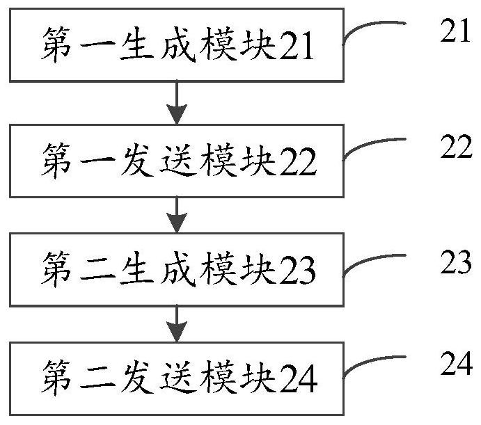
[0058] Corresponding to the aforementioned method for time synchronization of multiple sensors, the present application also provides an embodiment of a device for time synchronization of multiple sensors.
[0059] figure 2 It is a block diagram of a multi-sensor time synchronization apparatus according to an exemplary embodiment. According to an embodiment of the present application, a multi-sensor time synchronization device is provided, including:
[0060] The first generation module 21 is used to receive the initial time stamp timing sent by the host computer, and according to the initial time stamp timing, start the internal timer and generate two mutually independent first trigger pulse signals and second trigger pulse signals;
[0061] The first sending module 22 is used to send the count value of the second trigger pulse signal and the internal timestamp for generating the second trigger pulse signal to the host computer, and the count value and the internal timestamp are used for To achieve matching and alignment with sensor data on the host computer;
[0062] The second generation module 23 is used for simulating the function of the GPS receiver, generating the pulse-per-second synchronization signal and the time message, and sending the pulse-per-second synchronization signal and the time message to the first sensor and the second sensor, so as to make the sensor Realize internal timing synchronization with the time master device;
[0063] The second sending module 24 is configured to send the first trigger pulse signal and the second trigger pulse signal to the second sensor and the third sensor respectively, so as to trigger the second sensor and the third sensor to perform data collection, and Send the collected data to the upper computer.
[0064] Regarding the apparatus in the above-mentioned embodiment, the specific manner in which each module performs operations has been described in detail in the embodiment of the method, and will not be described in detail here.
[0065] For the apparatus embodiments, since they basically correspond to the method embodiments, reference may be made to the partial descriptions of the method embodiments for related parts. The device embodiments described above are only illustrative, wherein the units described as separate components may or may not be physically separated, and the components displayed as units may or may not be physical units, that is, they may be located in One place, or it can be distributed over multiple network elements. Some or all of the modules can be selected according to actual needs to achieve the purpose of the solution of the present application. Those of ordinary skill in the art can understand and implement it without creative effort.
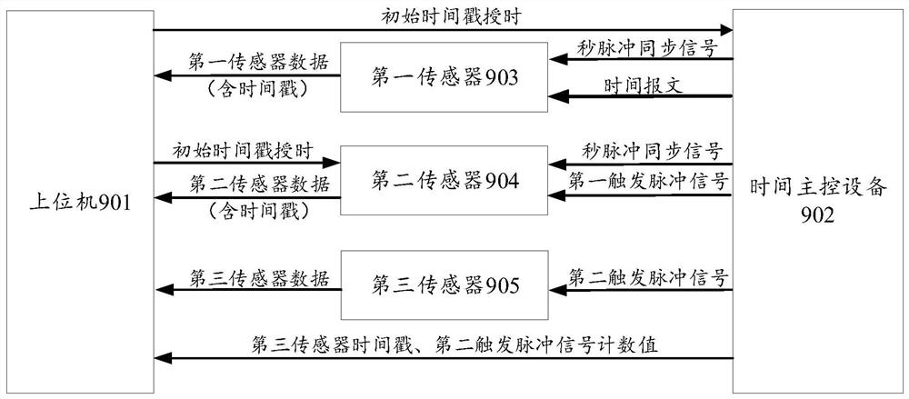
[0066] Correspondingly, the embodiment of the present application also provides a multi-sensor time synchronization system, image 3 It is a block diagram of a multi-sensor time synchronization system according to an exemplary embodiment. refer to image 3 , the system includes:
[0067]The host computer 901 is used to provide initial timing for the time master device and the second sensor, and to receive sensor data and time stamps returned by the time master device and each sensor, and to match and align the time stamps;
[0068] The time master control device 902 is used to obtain the internal time stamp after receiving the time service from the host computer, and uses the internal timer to generate a second pulse synchronization signal and two trigger pulse signals to send to each sensor, and at the same time according to the camera trigger frequency. The value is sent to the upper computer; and the analog GPS receiver function sends the timing message to the sensor. Specifically, as Figure 4 As shown in the figure, after the time master device is powered on, it performs interrupt configuration, serial port initialization, timer initialization and PWM output pulse configuration successively. After the initial timing of the upper computer arrives, each timer is turned on and the trigger pulse signal required by each sensor is sent. And the second pulse synchronization signal; send the time message to the first sensor through the UART serial interface, and send the time stamp and pulse count value of the third sensor to the upper computer through another UART interface.
[0069] The first sensor 903 is used to receive the time-serving message and the second pulse synchronization signal of the time master device, collect sensor data after completing the time synchronization function with the time master device internally, and combine the data with the internally generated time stamp. and sent to the host computer. In this embodiment, the first sensor is a laser radar as an example.
[0070] The second sensor 904 is used to receive the pulse-per-second synchronization signal and the trigger pulse signal of the time master device, internally realize timing synchronization with the time master device according to the pulse-per-second synchronization signal, collect sensor data according to the frequency of the trigger pulse signal, and Send the data together with the internally generated timestamp to the host computer. In this embodiment, the second sensor is an IMU as an example.
[0071] The third sensor 905 is used to receive the trigger pulse signal of the time master device, collect sensor data according to the frequency of the trigger pulse signal, and send the data to the host computer. In this embodiment, the third sensor is a camera as an example.
[0072] Correspondingly, an embodiment of the present application further provides an electronic device, including: one or more processors; a memory for storing one or more programs; when the one or more programs are processed by the one or more programs The processor executes such that the one or more processors implement the method as described above.
[0073] Correspondingly, according to an embodiment of the present application, there is also provided a computer-readable storage medium on which computer instructions are stored, characterized in that, when the instructions are executed by a processor, the steps of the above method are implemented.
[0074] The above-mentioned serial numbers of the embodiments of the present application are only for description, and do not represent the advantages or disadvantages of the embodiments.
[0075] In the several embodiments provided in this application, it should be understood that the disclosed technical content can be implemented in other ways. The device embodiments described above are only illustrative, for example, the division of the units may be a logical function division, and there may be other division methods in actual implementation, for example, multiple units or components may be combined or Integration into another system, or some features can be ignored, or not implemented. On the other hand, the shown or discussed mutual coupling or direct coupling or communication connection may be through some interfaces, indirect coupling or communication connection of units or modules, and may be in electrical or other forms.
[0076] The units described as separate components may or may not be physically separated, and components shown as units may or may not be physical units, that is, may be located in one place, or may be distributed to multiple units. Some or all of the units may be selected according to actual needs to achieve the purpose of the solution in this embodiment.
[0077] In addition, each functional unit in each embodiment of the present application may be integrated into one processing unit, or each unit may exist physically alone, or two or more units may be integrated into one unit. The above-mentioned integrated units may be implemented in the form of hardware, or may be implemented in the form of software functional units.
[0078] The integrated unit, if implemented in the form of a software functional unit and sold or used as an independent product, may be stored in a computer-readable storage medium. Based on this understanding, the technical solutions of the present application can be embodied in the form of software products in essence, or the parts that contribute to the prior art, or all or part of the technical solutions, and the computer software products are stored in a storage medium , including several instructions for causing a computer device (which may be a personal computer, a server, or a network device, etc.) to execute all or part of the steps of the methods described in the various embodiments of the present application. The aforementioned storage medium includes: U disk, read-only memory (ROM, Read-Only Memory), random access memory (RAM, Random Access Memory), mobile hard disk, magnetic disk or optical disk and other media that can store program codes .
[0079] The above descriptions are only preferred embodiments of the present invention, and are not intended to limit the present invention. Any modifications, equivalent replacements, improvements, etc. made within the spirit and principles of the present invention shall be included in the scope of the present invention. within the scope of protection.

PUM

no PUM

Description & Claims & Application Information

We can also present the details of the Description, Claims and Application information to help users get a comprehensive understanding of the technical details of the patent, such as background art, summary of invention, brief description of drawings, description of embodiments, and other original content. On the other hand, users can also determine the specific scope of protection of the technology through the list of claims; as well as understand the changes in the life cycle of the technology with the presentation of the patent timeline. Login to view more.

Similar technology patents

Electric energy meter verification device control method and system independent of equipment

InactiveCN110501666AReduced complexity and maintenance costsGood scalability and portability
Owner:JIANGSU FRONTIER ELECTRIC TECH +2

Classification and recommendation of technical efficacy words

  • Good scalability and portability

Electric energy meter verification device control method and system independent of equipment

InactiveCN110501666AReduced complexity and maintenance costsGood scalability and portability
Owner:JIANGSU FRONTIER ELECTRIC TECH +2
Why Eureka
Try Eureka