Yarn drying and winding machine

A winding machine and yarn technology, applied in the directions of drying, drying solid materials, heating to dry solid materials, etc., can solve problems such as quality damage and yarn moldy, and achieve the effect of reducing operation troubles

Pending Publication Date: 2021-04-20
江雄
View PDF13 Cites 4 Cited by
  • Summary
  • Abstract
  • Description
  • Claims
  • Application Information

AI Technical Summary

Problems solved by technology

[0005] In order to overcome the disadvantages that the general winding machine can only wind up the yarn, it is easy to wind up the yarn that is not completely dried and cause the yarn to become moldy, resulting in quality damage. The purpose of the present invention is to provide an automatic Yarn Dryer Winder with Dryer

Method used


Image

  • Yarn drying and winding machine
  • Yarn drying and winding machine
  • Yarn drying and winding machine

Examples


Embodiment 1

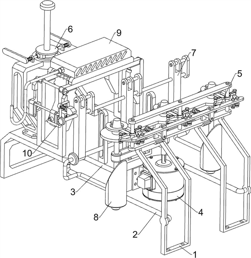
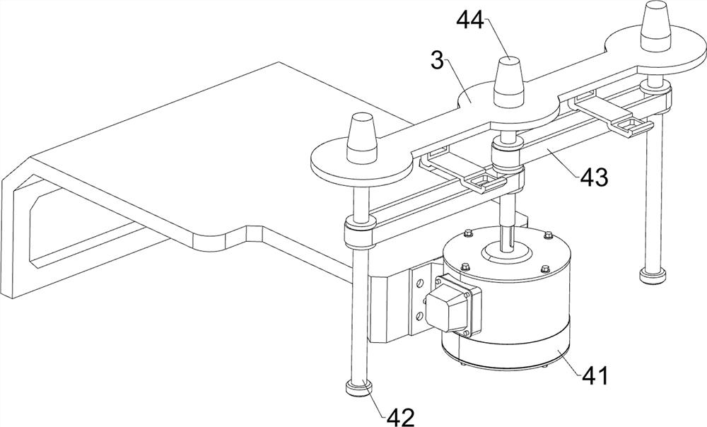
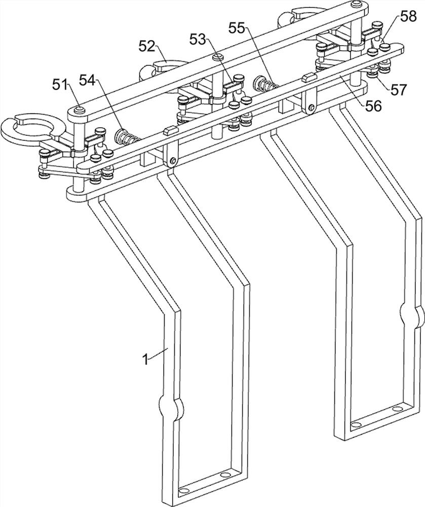
[0029] A yarn drying and winding machine, such as Figure 1 to Figure 4 As shown, it includes a bracket 1, a fixing rod 2, a mounting plate 3, a driving component 4, a clamping component 5 and a clamping component 6. The front and rear sides of the bracket 1 are welded with a fixing rod 2, and the left side of the fixing rod 2 is welded. A mounting plate 3 is connected between the two. The right side of the mounting plate 3 is provided with a driving component 4 , the upper side of the bracket 1 is provided with a clamping component 5 , and the upper side of the mounting plate 3 is provided with a clamping component 6 .

[0030] When the yarn needs to be wound up, the clamping component 6 is controlled to fix the yarn, and then the control yarn is divided into three strands and fixed on the clamping component 5 respectively, and then the driving component 4 is activated, and the driving component 4 will drive the yarn winding When the yarn is wound, close the drive assembly 4,...

Embodiment 2

[0038]On the basis of Example 1, as figure 1 , Figure 5 , Image 6 , Figure 7 and Figure 8 As shown, it also includes a guide assembly 7. The guide assembly 7 includes a second guide rail 71, a cross bar 72, a bar block 73, a first special-shaped bar 74, a fixed plate 75 and a limit bar 76. The front and rear of the mounting plate 3 The sides are welded with second guide rails 71 , a cross bar 72 is slidably connected between the second guide rails 71 , and three bar-shaped blocks 73 are connected evenly spaced on the cross-bar 72 , and a first special-shaped rod is connected between the bar-shaped blocks 73 . 74. Three fixed plates 75 are connected to the first special-shaped rod 74 at even intervals, and limit rods 76 are connected between the fixed plates 75 and the bar-shaped block 73.

[0039] When the yarn needs to be wound up, the control yarn is divided into three strands and passes between the limiting rod 76 and the first special-shaped rod 74 respectively, so...


PUM


Abstract

The invention relates to a winding machine, in particular to a yarn drying and winding machine. The invention provides a yarn drying and winding machine with a drying function. The yarn drying and winding machine comprises a support, fixing rods mounted on the two sides of the support, a mounting plate mounted between the fixing rods, a driving assembly mounted on the mounting plate, a clamping assembly mounted on the support, and a clamping assembly mounted on the mounting plate. The yarn drying and winding machine is provided with a guiding assembly, the moving position of yarn can be limited, and then the yarn is prevented from making contact and being wound together; the yarn drying and winding machine is provided with a pushing assembly, so that the yarn can be driven to move up and down, and the yarn can be uniformly wound around a winding barrel; and the yarn drying and winding machine is provided with a drying assembly, so that the device can dry the yarn during winding, and then part of the yarn which is not dried can be prevented from being wound.

Description

technical field [0001] The invention relates to a winding machine, in particular to a yarn drying winding machine. Background technique [0002] Yarn is a kind of textile, which is processed into products of a certain fineness from various textile fibers, which are used for weaving, rope making, thread making, knitting and embroidery. [0003] Generally, the yarn needs to be washed and disinfected after production. The washed and disinfected yarn needs to be manually picked up, dried and dried, and then wound up. The general winder can only wind the yarn. When winding the yarn Some incompletely dried yarns will be encountered. Winding the incompletely dried yarns will easily cause the yarns to become moldy, resulting in quality damage. [0004] Therefore, it is necessary to design a yarn drying and winding machine that can self-dry. SUMMARY OF THE INVENTION [0005] In order to overcome the shortcoming that the general winding machine can only wind the yarn, and the yarn...

Claims


Application Information

Patent Timeline
Patent Type & Authority Applications(China)
IPC IPC(8): B65H54/36B65H54/44B65H54/54B65H54/70B65H57/06F26B3/00
Inventor 不公告发明人
Owner 江雄
Why Eureka
Try Eureka