Electroplating equipment for two-side feeding and discharging of electroplated parts

A technology for electroplating equipment and electroplating parts, applied in the direction of electrolysis components, electrolysis process, cells, etc., can solve the problems of inability to rotate safety, hidden dangers and other problems of electroplating parts

Inactive Publication Date: 2021-04-20
苏州耀水源环境科技有限公司
View PDF0 Cites 0 Cited by
  • Summary
  • Abstract
  • Description
  • Claims
  • Application Information

AI Technical Summary

Problems solved by technology

[0003] The purpose of the present invention is to provide a kind of electroplating equipment for loading and unloading on both sides of the electroplating parts in order to solve the technical problems that the electroplating parts cannot be rotated when the existing electroplating equipment is working and there is a certain safety hazard in loading and unloading.

Method used


Image

  • Electroplating equipment for two-side feeding and discharging of electroplated parts
  • Electroplating equipment for two-side feeding and discharging of electroplated parts
  • Electroplating equipment for two-side feeding and discharging of electroplated parts

Examples


Embodiment Construction

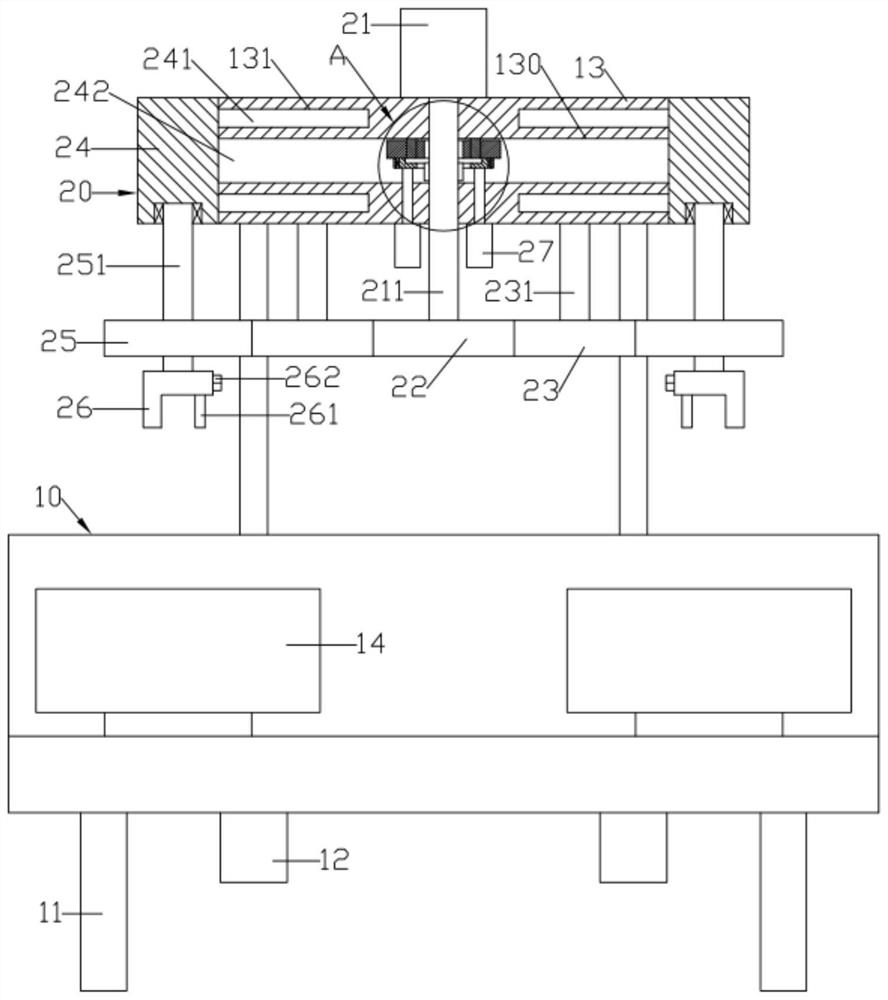
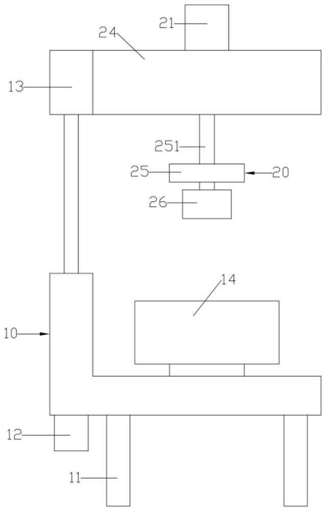
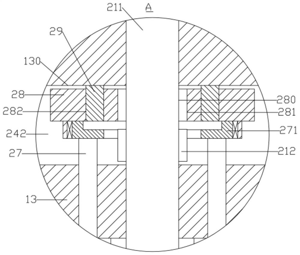
[0015] Such as Figure 1 ~ Figure 3 As shown, a kind of electroplating equipment for loading and unloading on both sides of an electroplating piece includes an L-shaped support frame 10 and a driving device 20; the bottom of the support frame 10 is provided with several support feet 11; The electroplating tank 14 arranged symmetrically on the left and right; the center lifting plate 13 is arranged up and down directly above the support frame 10; the left and right moving grooves 130 are formed on the center lifting plate 13; the driving device 20 includes a pair of left and right moving seats 24; A pair of left and right moving seats 24 are arranged on the left and right sides of the center lifting plate 13 for left and right movement respectively; the end faces of a pair of left and right moving seats 24 that are close to each other are formed with left and right driving racks 242 respectively; In the slot 130; a pair of left and right driving racks 242 are distributed front ...


PUM


Abstract

The invention discloses electroplating equipment for two-side feeding and discharging of electroplated parts. A pair of left-right moving seats are arranged on the left side and the right side of a central lifting plate in a left-right moving mode correspondingly. A central rotating column is rotationally arranged on the central lifting plate. The central rotating column vertically penetrates through a left-right moving groove and is provided with a central gear. The central gear is located between a pair of left and right driving racks and engaged with the pair of left and right driving racks. A clutch device is arranged in the left-right moving groove. The clutch device is used for separating and combining the central rotating column and the central gear. A central driving gear is arranged at the bottom of the central rotating column. The lower end surface of the central lifting plate is pivoted with a pair of transmission central shafts which are symmetrically arranged left and right. A central transmission gear is fixed at the bottom of the transmission central shaft. A side central column is pivoted to the bottom surface of the left-right moving seat. A rotary gear is fixed to the lower portion of the side central column.

Description

technical field [0001] The invention relates to the technical field of electroplating equipment, in particular to an electroplating equipment for loading and unloading on both sides of an electroplating piece. Background technique [0002] At present, in the existing electroplating process, the plated parts are only statically immersed in the electroplating solution in the electroplating tank and electroplated, so that the concentration of the electroplating solution that can be touched by different positions of the plated parts is slightly different, so that the coating on the surface of the plated parts is not uniform enough. , in order to improve the uniformity of the coating, it is necessary to design a device that can rotate the hanger and the plated parts in the electroplating tank, so that different parts of the surface of the plated parts can contact more electroplating solution; In this way, if you do not pay attention to loading and unloading, the electroplated par...

Claims


Application Information

Patent Timeline
Patent Type & Authority Applications(China)
IPC IPC(8): C25D17/00C25D17/08C25D21/10
Inventor 胡跃炎
Owner 苏州耀水源环境科技有限公司
Why Eureka
Try Eureka