Auxiliary diversion device for agricultural irrigation canal

An agricultural irrigation and diversion device technology, applied in the agricultural field, can solve problems such as inconvenience, inconvenient farmland irrigation work, uneven farmland irrigation, etc., and achieve the effect of avoiding excessive irrigation

Active Publication Date: 2022-05-24
阳江市漠阳香农业发展有限公司
View PDF5 Cites 0 Cited by
  • Summary
  • Abstract
  • Description
  • Claims
  • Application Information

AI Technical Summary

Problems solved by technology

[0003] However, before and after the irrigation of these canals, the user needs to open and block the farmland, which is very inconvenient, and in the process of irrigation, it is necessary to observe the irrigation status of the farmland and successively open and block multiple farmlands. If multiple farmlands are connected at one time, there will be too much water in the farmland near the pumping place, and too little water in the farmland far away from the pumping place, which will make the irrigation of the farmland uneven, which will greatly inconvenient for users to carry out large-scale irrigation. Farm irrigation work

Method used


Image

  • Auxiliary diversion device for agricultural irrigation canal
  • Auxiliary diversion device for agricultural irrigation canal
  • Auxiliary diversion device for agricultural irrigation canal

Examples


Embodiment 1

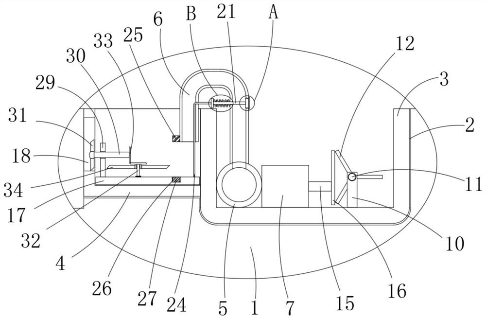
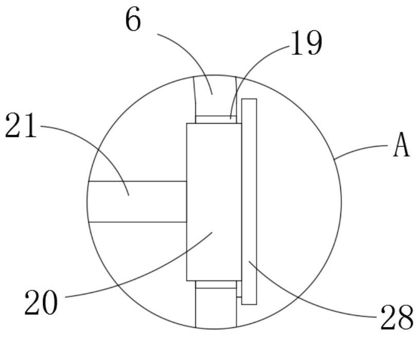
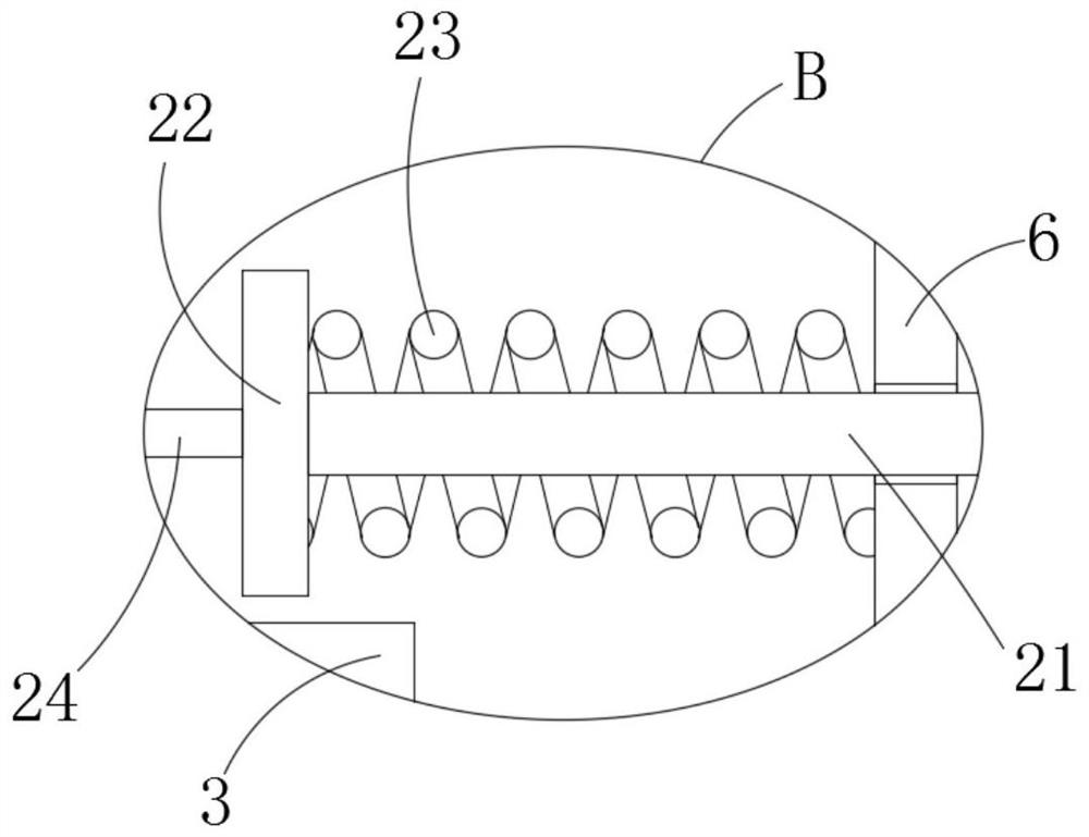
[0023] refer to Figure 1-4 , an auxiliary shunt device for agricultural irrigation canals, comprising a groove 2 arranged on a field ridge 1, a canal seat 3 is fixedly connected on the inner wall of the groove 2, the canal seat 3 is arranged in a U shape, and the canal seat 3 is provided with a plurality of A drainage device, the drainage device includes a working box 4 fixedly connected to the outer wall of the canal seat 3, one end of the working box 4 away from the canal seat 3 is arranged through the field ridge 1, and the inner wall of the canal seat 3 is fixedly connected with a water flow pipe 5, and the water flow pipe 5 A drainage tube 6 is fixedly connected to the outer wall of the upper end of the drainage tube 6. The end of the drainage tube 6 away from the water flow tube 5 is located in the working box 4. The drainage tube 6 is arranged in a U shape. 7 is arranged close to one end of the water flow pipe 5, and a side wall of the workbench 7 close to the water fl...

Embodiment 2

[0029] refer to figure 1 , the difference between this embodiment and the first embodiment is the setting of the supporting rod 29 and other devices, the upper end surface of the buoyancy plate 17 is fixedly connected with a supporting rod 29, the supporting rod 29 is set close to the watering hole 18, and the supporting rod 29 is rotated and connected with a rotating Rod 30, one end of the rotating rod 30 close to the watering hole 18 is fixedly connected with a water flow fan blade 31, the water flow fan blade 31 is arranged in the watering hole 18, the upper end surface of the buoyancy plate 17 is rotatably connected with a rotating shaft 32, and the rotating shaft 32 is far away from the buoyancy One end of the plate 17 and the end of the rotating rod 30 away from the water flow fan blade 31 are fixedly connected with a helical gear 33, the two helical gears 33 are arranged in mesh with each other, and the upper floating fan blade 34 is fixedly connected to one end of the r...


PUM


Abstract

The invention discloses an auxiliary flow diversion device for an agricultural irrigation canal, which comprises a groove arranged on a field ridge, and a water channel seat is fixedly connected to the inner wall of the groove, and the water channel seat is arranged in a U shape. A plurality of drainage devices are provided, and the drainage device includes a working box fixedly connected to the outer wall of the drainage seat. A drainage tube is fixedly connected to the outer wall of the upper end of the water flow tube, and the end of the drainage tube away from the water flow tube is located in the working box. In the present invention, the user no longer needs to excavate and connect the farmland to complete the irrigation work smoothly and conveniently. At the same time, the water inflow of the farmland can be effectively controlled, and then the situation of excessive irrigation of the farmland can be effectively avoided, which greatly facilitates the use of the user. .

Description

technical field [0001] The invention relates to the technical field of agriculture, in particular to an auxiliary diversion device for an agricultural irrigation canal. Background technique [0002] In agricultural production activities, in order to improve the irrigation efficiency of farmland, corresponding irrigation canals will be excavated and constructed. When irrigation work is required, it is only necessary to open the connection between the canal and the farmland, and then the water in the river channel is pumped into the water through the pump. The irrigation work of the farmland can be successfully completed in the canal. [0003] However, before and after the irrigation of these canals, the user needs to open and block the farmland, which is very inconvenient. In the process of irrigation, it is necessary to observe the irrigation status of the farmland to open and block multiple farmlands in turn. If all the farmlands are opened up at one time, the water volume...

Claims


Application Information

Patent Timeline
Patent Type & Authority Patents(China)
IPC IPC(8): F03B13/00E02B13/00F16K3/02F16K3/30F16K31/30F16L55/10
Inventor 赖惠琼
Owner 阳江市漠阳香农业发展有限公司
Why Eureka
Try Eureka