Combined supporting structure for treating dangerous rock mass and construction method thereof

A technology of combined support and dangerous rock mass, which is applied in infrastructure engineering, excavation, construction, etc., can solve the problems that the safety and stability of dangerous rock mass cannot be guaranteed, the safety and stability cannot be guaranteed, and the reinforcement treatment measures are single. The effect of low equipment requirements, good economy, and simple design and composition

Pending Publication Date: 2021-04-20
中国水电顾问集团贵阳勘测设计研究院岩土工程有限公司 +1
View PDF5 Cites 3 Cited by
  • Summary
  • Abstract
  • Description
  • Claims
  • Application Information

AI Technical Summary

Problems solved by technology

[0006] The problem with the maintenance structure of the first type of large-scale dumped dangerous rock mass is that the reinforcement treatment measures are single. When the scale of the dangerous rock mass is large or cannot be removed by blasting, it is often difficult to achieve the treatment effect by using a single treatment method. Security and stability cannot be guaranteed
The problem with the second dumping and destruction type dangerous rock mass management method is that when the development stability of the cracks and interlayers in the dangerous rock mass is poor, opening horizontal holes in the weak layer below the dangerous rock mass will cause a relatively high construction risk.
The problem with the third type of rapid reinforcement device for slope dangerous rock mass is that the method adopted for the maintenance structure is relatively simple, and it is difficult to ensure its safety and stability for large-scale and complex dangerous rock mass with wide cracks.
[0007] Therefore, the above prior art is still not ideal enough

Method used


Image

  • Combined supporting structure for treating dangerous rock mass and construction method thereof
  • Combined supporting structure for treating dangerous rock mass and construction method thereof

Examples


Embodiment Construction

[0025] The present invention will be further described in detail below in conjunction with the accompanying drawings and embodiments.

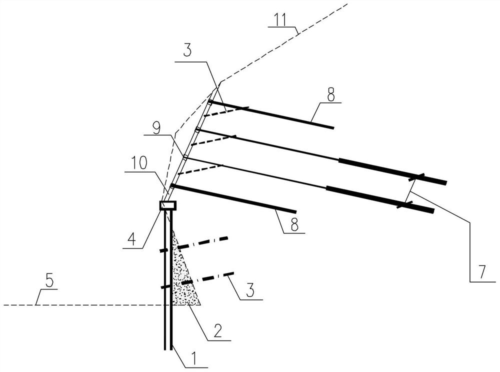
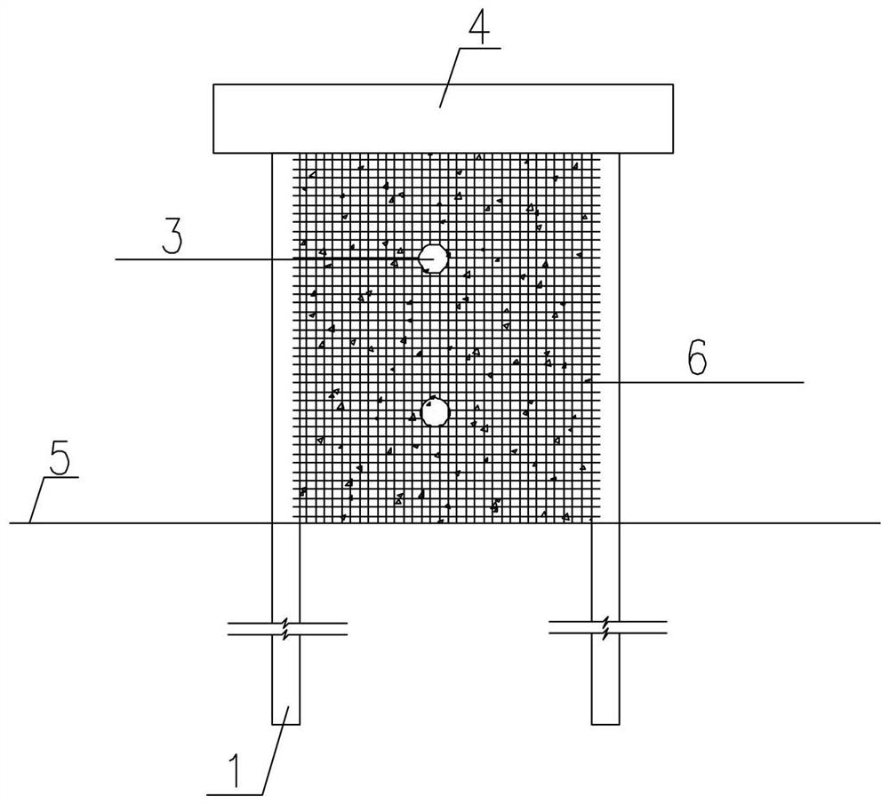
[0026] like figure 1 and figure 2 As shown, the structure of the present invention mainly includes micro steel pipe pile 1, concrete 2, PVC drainage pipe 3, pile top crown beam 4, ground 5, prefabricated concrete baffle 6, prestressed anchor cable 7, prestressed anchor rod 8, Sash girders 9, earth backfill 10, original topographic line 11 of dangerous rock mass and other parts. During specific implementation, a double-row miniature steel pipe pile 1 is designed in the lower dangerous rock mass, including a circular hollow prefabricated steel pipe pile body with a diameter not greater than 300mm, and three steel tendons built in. less than 3m, to ensure that the micro-steel pipe pile 1 has a sufficient length of the embedded section, the top of the micro-steel pipe pile 1 is provided with a pile crown beam 4, and the double row of micro-stee...


PUM


Abstract

The invention discloses a combined supporting structure for treating dangerous rock mass and a construction method thereof. The combined supporting structure comprises micro steel pipe piles arranged in two rows on the lower dangerous rock mass, wherein pile top crown beams are arranged at the tops of the micro steel pipe piles; prefabricated concrete baffles are arranged between the micro steel pipe piles, the prefabricated concrete baffles are covered with meshes in a net hanging and spraying mixing mode, and PVC drainage pipes are arranged in the micro steel pipe piles; backfill concrete is adopted between the micro steel pipe piles and the dangerous rock mass for backfill treatment; and frame beams are arranged on the upper slope surface of the dangerous rock mass, prestressed anchor cables or anchor rods are arranged at the joints of the frame beams, the bottoms of the frame beams extend to the pile top crown beams, backfill soil is arranged in the frame beams, and grass seeds are planted in the backfill soil to play a greening role. Due to the fact that the construction speed of the micro piles is high, the development of deformation of the dangerous rock mass can be preliminarily controlled within a short time, and high efficiency is achieved; and meanwhile, the pile diameter of the micro steel pipe piles is small, the design composition is simple, the requirement for driving equipment is not high, and good economic efficiency is achieved.

Description

technical field [0001] The invention relates to a treatment method for a dangerous rock mass that may develop into a landslide, in particular to a combined support structure for treating a dangerous rock mass and a construction method thereof. Background technique [0002] Dangerous rock masses are mostly located on steep slopes or cliffs and are cut by multiple groups of structural planes. Although they have not yet experienced instability, they have already met the conditions for instability and failure. Under gravity, weathering force, earthquake, seepage pressure and external environment Under the action of external forces such as vibration interference, it may lead to instability and failure of separation from the parent rock, resulting in casualties or property losses below, which is a typical geological disaster. The methods related to the management of dangerous rock mass in the prior art generally have the following several types: [0003] The first is a large-scal...

Claims


Application Information

Patent Timeline
Patent Type & Authority Applications(China)
IPC IPC(8): E02D17/20
Inventor 蒲黍絛
Owner 中国水电顾问集团贵阳勘测设计研究院岩土工程有限公司
Why Eureka
Try Eureka