Solidified soil retaining wall and construction method thereof

A construction method and technology for solidifying soil, which can be used in excavation, artificial islands, water conservancy projects, etc., can solve problems such as large construction costs, and achieve the effects of short construction period, ecological environment protection, and good frost resistance.

Active Publication Date: 2015-06-03
福建省建专岩土工程有限公司 +1
View PDF8 Cites 7 Cited by
  • Summary
  • Abstract
  • Description
  • Claims
  • Application Information

AI Technical Summary

Problems solved by technology

During the construction of the retaining wall, a large amount of earthwork excavation and backfilling work is required, and the construction cost is high.

Method used


Image

  • Solidified soil retaining wall and construction method thereof
  • Solidified soil retaining wall and construction method thereof
  • Solidified soil retaining wall and construction method thereof

Examples


Embodiment 1

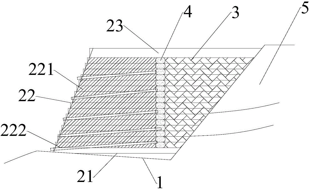
[0045] Please refer to image 3 , a solidified soil retaining wall according to the present invention, comprising a foundation groove 1 arranged near the side slope 5, the foundation groove 1 is divided into a solidified soil mixture laying area and a filling area;

[0046] The solidified soil mixture laying area includes the paving top layer 23, the paving middle layer 22 and the paving bottom layer 21 laid up and down in sequence to form a wall body, and a plurality of drainage pipes 222 are buried obliquely in the body of the wall, and the drainage pipes 222 The water inlet extends into the filling area, the water outlet of the drainage pipe 222 is inclined to the bottom of the foundation tank 1, and a plurality of drainage pipes 222 are arranged up and down; one end of the paving bottom layer 21 touches the top slope 5; the paving middle layer 22 includes a multi-layer solidified soil mixture layer 221, and a filling area is reserved at one end of the paving middle layer 2...

Embodiment 2

[0050] refer to Figure 4 , Figure 4 It is a cross-sectional view of a reinforced retaining wall with solidified soil. The reinforced retaining wall with solidified soil is an improvement based on Embodiment 1, specifically, paving any solidified soil mixture layer 221 and the corresponding plain soil layer 3 in the middle layer 22 Ribs 6 are laid on the upper floor. For the situation that the design height of the retaining wall is relatively high, the ribs 6 can be embedded during the paving process of the solidified soil retaining wall, and the ribs 6 extend to the fill soil behind the wall. The friction between the ribs 6 and the backfill of the wall is used to improve the engineering characteristics of the backfill of the wall, and the solidified soil retaining wall is combined with the reinforced soil to improve the retaining capacity of the retaining wall and increase the stability of the slope 5 .

Embodiment 3

[0052] refer to Figure 5 , Figure 5 It is a cross-sectional view of the solidified soil retaining wall with transverse ribs 7, which is an improvement based on the second embodiment. Specifically, the paving middle layer 22 also includes transverse ribs 7, and each transverse rib 7 It extends to the filling area at a preset vertical distance until it is laid to the side slope 5 , and the ribs 6 are pre-embedded in the transverse ribs 7 . During the layered paving and rolling process of the solidified soil reinforced retaining wall body and the backfill soil, the solidified soil paving operation is extended to the backfill layer at intervals of vertical intervals to form transverse ribs 7 . There is a great friction between the transverse rib 7 and the filling soil behind the wall. The existence of the transverse rib 7 increases the self-weight of the retaining wall at the same time. This type of retaining wall has a strong retaining capacity and can be used for retaining so...


PUM


Abstract

The invention discloses a solidified soil retaining wall and a construction method thereof. The solidified soil retaining wall is applied to support of side slopes. The method comprises the following steps: S01, lofting and treating a foundation trench: setting the long edge, wide edge and height lengths of the foundation trench, determining a foundation trench excavation sideline according to the practical lengths of the long edge and wide edge of the preset foundation trench, and lofting; S02, excavating the foundation trench: performing side slope excavation according to the excavation sideline and the foundation trench height after lofting to obtain original site soil, and leveling and rolling the bottom of the foundation trench, wherein one side close to the side slope is subjected to excavation according to a preset inclination angle; S03, stirring a solidified soil mixture: uniformly stirring the original site soil, cement and a curing agent solution according to a set mixture ratio to obtain the solidified soil mixture; S04, paving a wall body and refilling plain soil; S05, curing the wall body. By adopting the scheme, materials can be obtained from local sources, and the construction cost is reduced; the construction period can be shortened; energy is saved, and environmental friendliness is facilitated, furthermore the comprehensive performance of the wall body can be enhanced.

Description

technical field [0001] The invention relates to slope support technology in the field of geotechnical engineering, in particular to a solidified soil retaining wall and a construction method thereof. Background technique [0002] A retaining wall refers to a structure that supports roadbed fill or hillside soil and prevents the deformation and instability of fill or soil. Traditional retaining wall types include gravity type, cantilever type, buttress type and reinforced earth retaining wall, etc. Gravity type retaining wall refers to a retaining wall that relies on the wall's own weight to resist the lateral pressure of the soil. Gravity retaining walls can be used as masonry blocks, flakes, and prefabricated concrete blocks, or integrally poured with flake concrete and concrete. The cantilever retaining wall is composed of a base plate and a straight wall fixed on the base plate. The stable retaining wall is mainly maintained by the filling weight on the base plate. It is...

Claims


Application Information

Patent Timeline
Patent Type & Authority Applications(China)
IPC IPC(8): E02D29/02
CPCE02D17/20E02D29/02
Inventor 简洪钰
Owner 福建省建专岩土工程有限公司
Why Eureka
Try Eureka