Particle damper

A particle damper and a technology of damping particles, applied in the direction of building types, buildings, building components, etc., can solve the problems of poor shock absorption control effect, amplified structural dynamic response, and the difficulty of traditional particle dampers in exerting vibration reduction control effects. Achieve the effect of simple structure and reduce structural damage or collapse

Active Publication Date: 2021-04-20
BEIJING UNIV OF TECH +1
View PDF9 Cites 2 Cited by
  • Summary
  • Abstract
  • Description
  • Claims
  • Application Information

AI Technical Summary

Problems solved by technology

[0004] Therefore, the application and promotion of traditional particle dampers in civil engineering structures mainly have the following problems: (1) When the damping particles are piled up or the filling rate is low, it is difficult for traditional particle dampers to play an effective damping role in civil engineering structures. (2) Due to the limitation of particle vibration conditions, the traditional particle damper has poor vibration control effect in the early stage of civil engineering structure vibration (the structural dynamic is small), and may even amplify the dynamic response of the structure; (3) Traditional particle dampers must add a large mass (additional mass ratio is generally not less than 2%) to achieve a better shock absorption effect, and excessive additional mass may increase the cost of the structural design stage

Method used


Image

  • Particle damper
  • Particle damper
  • Particle damper

Examples


Embodiment 1

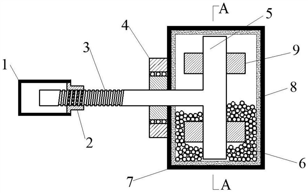
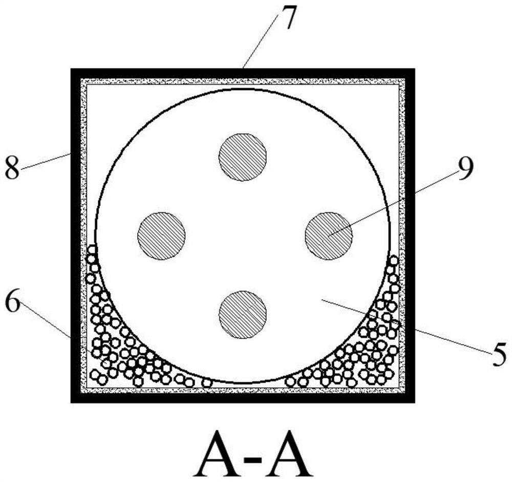
[0029] Such as figure 1 , figure 2 As shown, the particle damper provided in this example is mainly used between bridge piers and beams to play the role of shock absorption (vibration). Specifically, the particle damper includes a first fixed housing 1 , a nut 2 , a ball screw 3 , a bearing 4 , a flywheel 5 , damping particles 6 , a second fixed housing 7 , an energy dissipation layer 8 and a stirring rod 9 . Wherein, the first fixed housing 1 and the second fixed housing 7 are respectively welded on the abutment or main beam member, and the nut 2 is welded on the first fixed housing 1; the threaded end of the ball screw 3 is screwed to the nut 2 And inserted into the first fixed housing 1, the other end of the ball screw 3 is inserted into the second fixed housing 7 through the bearing 4; the flywheel 5 is arranged in the second fixed housing 7 and welded with the other end of the ball screw 3 Together, both sides of the flywheel 5 are welded with a number of stirring rods...

Embodiment 2

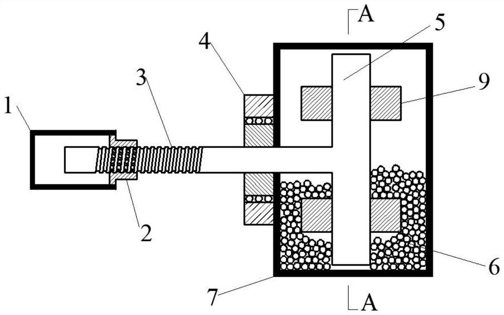
[0037] Such as image 3 , Figure 4 As shown, the particle damper provided in this example is mainly used in the interstory of high-rise buildings or in the buffer layer of blasting structures to play the role of shock absorption (vibration). Specifically, the particle damper includes a first fixed housing 1 , a nut 2 , a ball screw 3 , a bearing 4 , a flywheel 5 , damping particles 6 , a second fixed housing 7 and a stirring rod 9 . Wherein, the first fixed housing 1 and the second fixed housing 7 are respectively connected on the high-rise building layer by reserved bolts, and the nut 2 is welded on the first fixed housing 1; the threaded end of the ball screw 3 is screwed with the nut 2 connected and inserted into the first fixed housing 1, the other end of the ball screw 3 is inserted into the second fixed housing 7 through the bearing 4; the flywheel 5 is arranged in the second fixed housing 7 and connected with the other end of the ball screw 3 Welded together, a numbe...


PUM


Abstract

The invention discloses a particle damper. The particle damper comprises an inerter energy absorption mechanism and a friction energy dissipation mechanism, wherein the inerter energy absorption mechanism is installed on a controlled component and configured to rotate and generate inertia force when the controlled component vibrates, and then vibration energy of the controlled component is absorbed; and the friction energy dissipation mechanism is connected with the action end of the inerter energy absorption mechanism and configured to rotate along with the inerter energy absorption mechanism and generate a collision and / or friction effect when the inerter energy absorption mechanism rotates, so that the energy of the particle damper is consumed. The particle damper has the advantages of simple structure, low price, rich raw materials, convenient and fast installation and the like, has the dual functions of inerter energy absorption and damping particle energy dissipation, and can achieve the function of effectively absorbing and dissipating the energy of a controlled structure when the structure shakes (vibrates) slightly.

Description

technical field [0001] The invention relates to a damper, in particular to a particle damper with the functions of inertial energy absorption and frictional energy consumption, and belongs to the field of engineering vibration control. Background technique [0002] With the rapid increase of population and the development of social economy, the construction of complex engineering structures such as super high-rise structures, long-span spatial structures and long-span bridges has gradually become the main measure to solve urban congestion and meet multi-functional needs. However, the safety and comfort of the complex engineering structures mentioned above are significantly affected by accidental loads during operation. For example, the safety of complex engineering structures under the action of strong earthquakes and typhoons has always been the bottleneck restricting the popularization and application of such structures in complex and harsh environments. In view of this, ...

Claims


Application Information

Patent Timeline
Patent Type & Authority Applications(China)
IPC IPC(8): E04H9/02E04B1/98
Inventor 王洪国解梦飞谢飞许维炳褚锋张民顾瑞海张文学
Owner BEIJING UNIV OF TECH
Why Eureka
Try Eureka