Piston assembly of pneumatic actuator

A technology of pneumatic actuators and piston components, which is applied in the direction of engine components, valve operation/release devices, valve details, etc., can solve the problems of unfavorable device practicability and work efficiency, reduce safety, increase device work efficiency, etc., to achieve Prevent the piston assembly from collapsing, ensure stable operation, and increase practicality

Pending Publication Date: 2021-04-20
无锡鑫明自控阀业有限公司
View PDF0 Cites 0 Cited by
  • Summary
  • Abstract
  • Description
  • Claims
  • Application Information

AI Technical Summary

Problems solved by technology

[0004] (1) When the existing device is in use, after the telescopic spring inside the piston assembly works for a long time, the telescopic spring is deformed outside the range of elastic force, which will lead to the loss of elastic performance, resulting in a decline in the working effect of the device, and the spring works Over time, it will react with oxygen in the air to slowly oxidize, be corroded, and the material characteristics of the spring will change, thus making the elastic capacity weaker, greatly reducing the practical effect of the device, which is not conducive to increasing the device's performance. Work efficiency, so the operator needs to manually replace the telescopic spring inside the piston assembly, and the existing device is mostly a sealed structure formed in one piece, which cannot complete the replacement and maintenance of the piston assembly, so the spring inside the piston assembly loses elasticity or elasticity After weakening, the operator cannot complete the replacement of the telescopic spring, so the use cost of the device is relatively high. Once the spring wears too much and cannot be used, a whole piston assembly needs to be replaced, which greatly reduces the economic benefits of the device and is not conducive to Availability of the device
[0005] (2) When the existing device is in use, because the piston rod reciprocates for a long time, when the piston rod is too hard, once the force exceeds the deformation elastic force of the spring, the spring will be destroyed immediately and lose its elastic force, which greatly reduces the force of the piston rod. The practicability of the device, when the piston rod is too strong, the piston assembly may also have the problem of collapsing, which greatly reduces the safety of the device and is not conducive to the practicability and working efficiency of the device

Method used


Image

  • Piston assembly of pneumatic actuator
  • Piston assembly of pneumatic actuator
  • Piston assembly of pneumatic actuator

Examples


Embodiment Construction

[0024]Next, the technical solutions in the embodiments of the present invention will be apparent from the embodiment of the present invention, and it is clearly described, and it is understood that the described embodiments are merely embodiments of the present invention, not all of the embodiments. Based on the embodiments of the present invention, there are all other embodiments obtained without making creative labor without making creative labor premises.

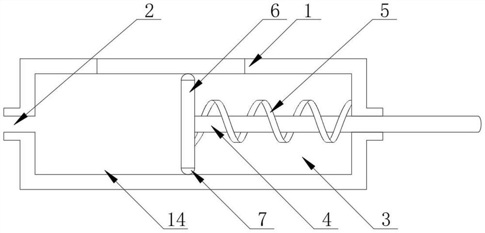
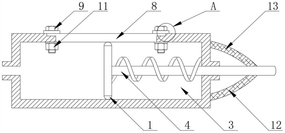
[0025]AppendFigure 1-4The piston assembly of a pneumatic actuator is, including the apparatus body 1, and the left end of the device body 1 is opened, and an inflatable chamber 14 is integrally formed in the left end of the device body 1, and the right side of the apparatus body 1 is opened. The piston chamber 3, the right end activity of the device body 1 is attached to the movable rod 4, and the surface of the movable rod 4 is fixedly mounted, and the left side of the movable rod 4 is integrally formed, and the surface of the p...


PUM


Abstract

The invention discloses a piston assembly of a pneumatic actuator, and particularly relates to the technical field of piston assemblies. The piston assembly comprises a device body, an air inlet is formed in the left end of the device body, an inflation chamber is integrally formed in the left end of the device body, and a piston chamber is formed in the right side of the device body. A movable rod is movably installed at the right end of the device body, a telescopic spring is fixedly installed on the surface of the movable rod, a push plate is integrally formed on the left side of the movable rod, a rubber ring is fixedly installed on the surface of the push plate, a fixing plate is detachably installed on the top face of the device body, and a fixing bolt is installed on the surface of the fixing plate in a threaded mode. By arranging an elastic rope, when the movable rod exerts excessive force, the elastic rope can effectively protect the telescopic spring from being stretched excessively, the safety of the device is greatly improved, and it is guaranteed that parts in the device work stably.

Description

Technical field[0001]The present invention relates to the field of piston assembly, and more particularly, the present invention relates to a piston assembly of a pneumatic actuator.Background technique[0002]The species and configuration of the adjustment mechanism of the pneumatic actuator is substantially the same, mainly to the actuator. Therefore, in the pneumatic actuator, the actuator and the adjustment valve are respectively composed of two parts of the actuator and the adjustment valve, according to the size of the control signal, generate corresponding thrust, push the adjustment valve action, the adjustment valve is pneumatic The adjustment portion of the actuator, under the action of the actuator thrust, the adjustment valve generates a certain displacement or corner, directly regulates the flow of the fluid, and the top of the piston is called on the center of the crankshaft rotation, and the nearest position is called down. Point, from the top dead center to the down de...

Claims


Application Information

Patent Timeline
Patent Type & Authority Applications(China)
IPC IPC(8): F16K31/122
Inventor 朱振华
Owner 无锡鑫明自控阀业有限公司
Why Eureka
Try Eureka