Blow-off pipe fixing device capable of reducing impact force and suitable for white spirit brewing
A technology of fixing device and sewage pipe, which is applied in the preparation of alcoholic beverages, siphon pipes, pipe components, etc., can solve the problems that the sewage pipe cannot continue to move up and down, and the effect of the protection of the sewage pipe is reduced.
- Summary
- Abstract
- Description
- Claims
- Application Information
AI Technical Summary
Problems solved by technology
Method used
Image

Examples
Embodiment Construction
[0022] The following will clearly and completely describe the technical solutions in the embodiments of the present invention with reference to the accompanying drawings in the embodiments of the present invention. Obviously, the described embodiments are only some, not all, embodiments of the present invention. Based on the embodiments of the present invention, all other embodiments obtained by persons of ordinary skill in the art without making creative efforts belong to the protection scope of the present invention.
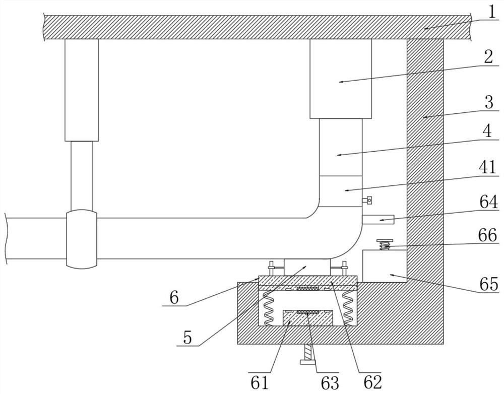
[0023] The present invention provides a technical solution: a sewage pipe fixing device suitable for liquor brewing that can reduce momentum, please refer to figure 1 , including brewing device body 1, sewage outlet 2, support plate 3 and sewage pipe 4;
[0024] see figure 1 , the top of the sewage outlet 2 is connected with the outer wall of the bottom of the brewing device body 1, the bottom of the sewage outlet 2 is slidingly connected with the sewage pipe...
PUM
 Abstract
Description
Claims
Application Information
 - R&D
- Intellectual Property
- Life Sciences
- Materials
- Tech Scout
- Unparalleled Data Quality
- Higher Quality Content
- 60% Fewer Hallucinations
Browse by: Latest US Patents, China's latest patents, Technical Efficacy Thesaurus, Application Domain, Technology Topic, Popular Technical Reports.
© 2025 PatSnap. All rights reserved.Legal|Privacy policy|Modern Slavery Act Transparency Statement|Sitemap|About US| Contact US: help@patsnap.com