Concrete impact resistance detection equipment

A detection equipment and concrete technology, applied in the field of impact resistance detection equipment, can solve the problems of inaccurate detection results, less manual participation, waste of time, etc., and achieve the effects of improving detection efficiency, good cleaning effect, and accurate data

Inactive Publication Date: 2021-04-20
陈志
View PDF0 Cites 1 Cited by
  • Summary
  • Abstract
  • Description
  • Claims
  • Application Information

AI Technical Summary

Problems solved by technology

[0005] In order to overcome the shortcomings of time-consuming, low efficiency and inaccurate detection results caused by manual participation in the detection, the technical problem to be solved is: to provide a concrete impact resistance detection equipment with less manual participation and high detection efficiency

Method used


Image

  • Concrete impact resistance detection equipment
  • Concrete impact resistance detection equipment
  • Concrete impact resistance detection equipment

Examples


Embodiment 1

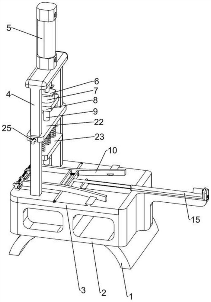
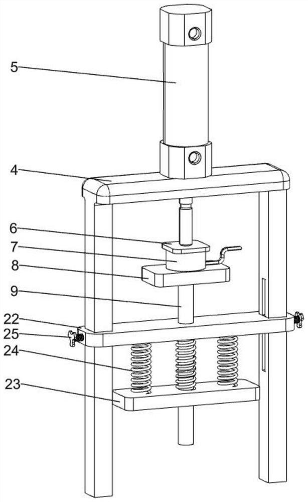
[0025] A concrete impact testing equipment, such as Figure 1-4 As shown, it includes a table leg 1, a base 2, a base plate 3, a bracket 4, an impact device, a clamping device and a pushing device, the base 2 is fixedly installed on the table leg 1, the base plate 3 and the bracket 4 are fixedly installed on the base 2 Fixedly installed on the upper left side of the base plate 3, the impact device is installed on the bracket 4, the clamping device is installed on the upper left side of the base plate 3, the clamping device is below the impact device, the pushing device is installed on the upper right side of the base plate 3, and the pushing device On the right side of the clamping device.

[0026] The table leg 1 plays a supporting role for the whole device, the bottom plate 3 plays a supporting role for the bracket 4, and the base 2 plays a supporting role for the whole device. When testing the strength of building concrete, the impact device is raised first, and then the re...

Embodiment 2

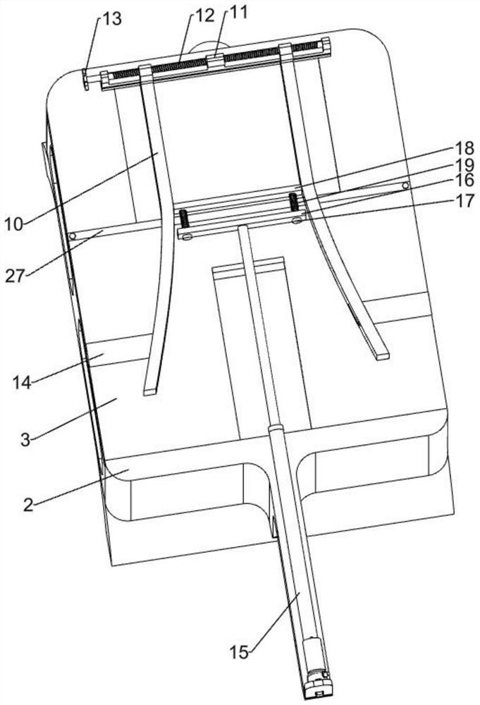
[0034] On the basis of Example 1, such as figure 2 , Figure 5-7As shown, also include slide plate 20, baffle plate 2001, second spring 21 and scraper 27, have two rectangular holes on the base plate 3, the left end of slide plate 20 is under the left side rectangular hole, the right end of slide plate 20 is on the right side Under the rectangular hole, the slide plate 20 is slidingly connected with the base plate 3, the baffle plate 2001 is installed on the upper right side of the slide plate 20, the baffle plate 2001 is higher than the base plate 3, and four second springs 21 are fixedly installed between the right side of the slide plate 20 and the base plate 3 , the scraper 27 is installed on the right end of the left rectangular hole on the bottom plate 3, and the scraper 27 is in contact with the slide plate 20.

[0035] When the test is over, the electric push rod 15 will shrink back. During the shrinking process, the first push plate 16 will contact the baffle plate ...


PUM


Abstract

The invention relates to impact resistance detection equipment, in particular to concrete impact resistance detection equipment. The technical problem to be solved is to provide the impact resistance detection equipment for the concrete precast slab, which is less in manual participation and high in detection efficiency. According to the technical scheme, the concrete impact resistance detection equipment comprises table legs, a base, a bottom plate, a support, an impact device, a clamping device and the like. Wherein the base is fixedly arranged on the table legs, a bottom plate is fixedly arranged on the base, the support is fixedly arranged above one side of the bottom plate, the impact device is arranged on the support, the clamping device is arranged above one side of the bottom plate, and the clamping device is arranged below the impact device. An electromagnet, the iron plate and an impact column are additionally arranged, manual participation is reduced through the installation of the electromagnet, the iron plate and the impact column, the detection efficiency is improved, the impact column can control force to impact the center position through the installation of a long plate and a third spring, the impact frequency is reduced, and obtained data are more accurate.

Description

technical field [0001] The invention relates to an anti-shock detection device, in particular to a concrete anti-shock detection device. Background technique [0002] Concrete refers to the collective name of engineering composite materials that use cementitious materials to cement aggregates into a whole In terms of construction, the impact resistance of concrete is extremely important. [0003] Nowadays, the concrete impact test is to put the concrete prefabricated slab on the slab, and drop the heavy object from a high altitude for impact. This method is a waste of manpower and time, and the efficiency is very low. Sometimes it takes multiple impacts to achieve the goal. Multiple impacts may also cause cracks in the precast concrete slab, making the test results inaccurate. [0004] Therefore, it is urgent to develop a concrete impact resistance testing equipment that can adjust the impact force, reduce manual participation, and improve work efficiency. Contents of th...

Claims


Application Information

Patent Timeline
Patent Type & Authority Applications(China)
IPC IPC(8): G01N3/30
Inventor 陈志
Owner 陈志
Why Eureka
Try Eureka