Low-power-consumption key destroying device

A technology of destroying keys and key buttons, which is applied in the field of low-power consumption destroying devices, and can solve problems such as conflicts, affecting user experience, and inability to adjust the design

Active Publication Date: 2021-04-20
武汉船舶通信研究所
8 Cites 0 Cited by

AI-Extracted Technical Summary

Problems solved by technology

This makes the safety protection design of many motherboards repeated in actual use, which may conflict with each other in actual use.
At the same time, since the security protection functions are all integrated on the main board, it is impossible to adjust the design for the relevant modules of the security protection function separately, so that the product ha...

Method used

The design idea of ​​the present invention is: get rid of the complicated circuit structure of existing similar products, carry out modular design to realize the core processing part of destroying the key function, improve the integration degree of board level while also reducing the structure of the module size. Since the key destroying module is not integrated with other functional motherboards, the energy consumption of the device it...

Abstract

The invention discloses a low-power-consumption key destroying device which comprises a main board area, a power supply area, a key destroying module, an external power supply battery bin, a front panel area, a rear panel area, a left uncovering key, a right uncovering key, a front panel key destroying key and a water inlet sensor. The front panel key destroying key is arranged on the front panel area, the left uncovering key and the right uncovering key are respectively arranged on two sides of a cover plate connected between the front panel area and the rear panel area; the key destroying module performs information interaction with the control panel of the main board area through an interface; the key destroying module is electrically connected with the left uncovering key, the right uncovering key, the front panel key destroying key and the water inlet sensor through GPIO pins and used for enabling the key destroying module to conduct key destroying operation after receiving the switching value of a key destroying signal. According to the invention, various key-destroying trigger mechanisms under low power consumption are realized, and the key-destroying function under different scenes is realized through the detection of the semaphore and the cooperation of the circuit.

Application Domain

Programme controlComputer control +4

Technology Topic

Electrical batteryElectrical connection +5

Image

  • Low-power-consumption key destroying device
  • Low-power-consumption key destroying device
  • Low-power-consumption key destroying device

Examples

  • Experimental program(1)

Example Embodiment

[0027]The technical solutions in the present application embodiment will be described in conjunction with the drawings in the present application embodiment.
[0028]In the following description, the term "first", "second" is only the purpose used to describe, and cannot be understood as an indication or implies relative importance. The following description provides a plurality of embodiments of the invention, and can be replaced or combined between different embodiments, and thus the present invention can also be considered to include all possible combinations of the same and / or different embodiments. Thus, if one embodiment includes features A, B, C, another embodiment includes feature B, D, then the present invention should also be considered including one or more other possible combinations of A, B, C, D. Embodiments, although this embodiment may not have a clear text record in the following.
[0029]The following description provides examples and is not limited to the scope, applicability, or examples of the claims. The function and arrangement of the described element can be changed without departing from the scope of the invention. Each example can be appropriately omitted, replaced or add various processes or components. For example, the described method can be performed in a different order in the described order, and various steps can be added, omitted or combined. Further, the features described with respect to some examples can be combined into other examples.
[0030]The design idea of ​​the present invention is: in addition to the complicated circuit structure of the existing similar products, the core processing section of the key function will be modularly designed, and the structure size of the module is also reduced while improving the degree of plate integration. Since the desigrable module does not integrate with other functions, the designer's own energy loss is maximized, and the setting of low power devices inside the ignition module is set with a variety of power priority, ensuring Regardless of whether the other parts of the device are powered down or not, the desigrable module set can sustained to stabilize whether there is important information leakage risk through the sensor to further enhance the reliability of the safety equipment.
[0031]Seefigure 1 Taking an actual application scenario as an example, this application device is mostly used in the field of safety equipment, providing the user to complete the destruction of key storage space and emergencies, including: motherboard zone 1, power supply area 2, fan area 3, the ignition module 4, the external power supply battery bin 5, front panel region 6, the rear plate region 7, the left cover key 8, the right open cover 9, the front panel is the key button 10, the water sensor 11, the front The panel designer button 10 is disposed on the front panel region 6, and the left open cover key 8 and the right opening key 9 are respectively disposed on the cover of the front panel region 6 and the rear panel region 7, respectively. side. The device is fitted with an external battery (placed on the equipment casing, built-in battery bin), which is convenient for the user to complete the battery replacement without opening the device cover. When the criminals deliberate or force majeure is coming, the device provides an important information that opens the inspection, water detection, effectively preventing such events from bringing unfaudable losses to users. The size of the ignition module 4 may be 80 mm * 30 mm, preferably by the I2C interface or the UART (RS232 level mode) interface to perform information interaction with the control panel of the motherboard region 1. In addition to the lock key module 4, the interconnection is performed by a pair of power cords with 18650 (about 3700 mAh) cells in the external power supply battery bin 5. The valve key module 4 provides several GPIO pins, interconnected with the left cover key 8, the right opening key 9, the front panel key button 10, the inlet sensor 11, which accepts the amount of switches from the ignition signal. . When there is a case where the destroying device is present, the interconnected components detect the corresponding electrical signal, and transmit the desigrable signal to the destroy module 4, and the control of the destroy module 4 is destroyed on important information.
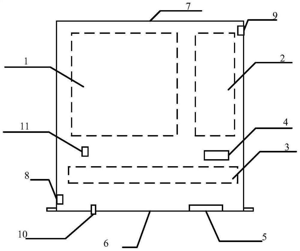
[0032]Specifically, the specific detection method of the illegal damage is that the device does not have the need to remove the device to remove the device, that is, when someone is trying to disassemble or destroy this device. When the external structure of the device, there is a hidden danger that there is a criminal or force majeure factor leading to internal information security. Since the lock key module 4 is electrically connected to the left cover key 8, the right open cover key 9, the front panel, the on-the-water sensor 11 is electrically connected, and when someone wants to dismantle the outer structure of the destroying device, the left openings key 8 , The right opening key 9, at least one of the front panel instructions 10 will be triggered and generated to generate an electrical signal to the ignition module 4, and the destroyable module 4 will destroy the store after receiving the corresponding electrical signal. information. In addition, when the device is soaked into the water because of human or force majeure, it may cause damage to the module or chip short circuit within the device. In order to avoid the device to be damaged by human damage, it is important to remove the module repair after the lock function is fed. The water sensor 11 also transmits an electrical signal to the ignition module 4 to destroy data to the calibration of the ignition module 4 in accordance with the existence of a liquid in the device.
[0033]In one embodiment, iffigure 2 As shown, the key module 4 is mainly composed of the following modules, a power management module, a power supply automatic switching circuit, a board, a power supply, and an acoustic optical and magnetic sensor
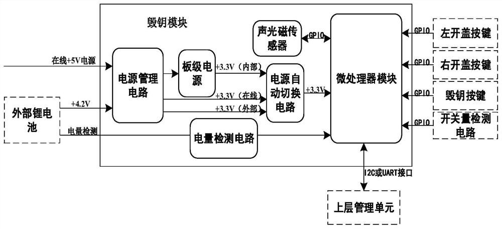
[0034]The microprocessor module completes the overall control and management functions of the apparatus of the present invention, as a preferred embodiment, the core device preferably uses ultra-low power consumption of 32-bit MCUs produced in China's large China's large semiconductor, using internal reliable SRAM and ROM resources, combined The interrupt resources inside the MCU are detected in real time for a variety of user switching signals. The power management module implements external power DC-DC conversion, external battery charging management, internal board-level power supply and other functions, its DC-DC conversion chip preferably selects low static power consumption LDO device models AX1205, complete online + 5V power supply to +3.33 V Power supply conversion, external battery charging management integrates transforctors and charging, management functions for external + 4.2V power supplies, and devices prefer to choose domestic devices. It is preferred to model LN2053; power supply automatic switching circuit implements online power supply, external battery power, internal The power state detection and automatic switching function of the board-level power supply. In order to greatly reduce the energy loss of the device itself, the device selects a low-voltage diode device, and its chip is preferably 1KE0.5A, which can achieve the following power supply priority: online power>External lithium battery power>Board Faram Capacitor Power. The board-level power supply is to meet the following scenario: When the power supply is powered down, the external battery power supply does not supply normally, the board-level power supply can provide a short-term power supply continuation function for the invention to the inventive device. The power detection circuit detects the external battery, when the electricity is below the predetermined threshold, the user is replaced by the sound of the motherboard area, the light alarm manner, while the circuit is also to avoid excessive plate energy Therefore, the power detection circuit does not use the current mainstream chip, but uses the resistance division circuit and combines the A / D conversion function that comes with the microprocessor module port, collecting the voltage obtained by the resistor divided into a number in real time and timely transition into a number. signal.
[0035]Specifically, a sound sensor, a brightness sensor, and an electromagnetic sensor can be integrated in the destroyed module, or an external sensor can be connected by an extended interface to provide a distributed mechanical state detection for the device. At the same time, it is also possible to monitor the environmental status of the device. When the unmanaged, electromagnetic or other non-physical means to steal important information, the destroyable module can also be detected by the sensor. When the sound, brightness, and electromagnetic signal detected by the sensor exceeds the preset threshold, it is considered that the environment in which the device is abnormal, for information security, the destroyed module will destroy important information.
[0036]In one embodiment, ifimage 3As shown, the microprocessor module is made of a microprocessor (MCU), a random memory (SRAM), program read only memory (ROM), hardware watchdog circuit (WDT), clock circuit, reset circuit, RTC circuit, timer circuit , I2C controller circuit, UART controller circuit consists.
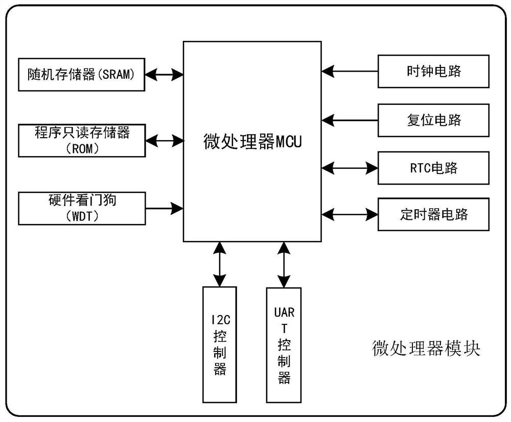
[0037]The microphone Unit, MCU is preferably an ultra-low power consumption series of Warrior Semiconductors with a model HC32L130. The interior has 16KB SRAM and 64KB Flash. SRAM is used to the program protected area, which is used to store password components (key information), etc., Flash is used to store the running control firmware. The hardware watchdog circuit (WDT) is used as the internal integrated circuit of the microprocessor, and the working state of the device of the present invention is monitored in real time. Once the program runs, the phenomenon of the crash, the watchdog circuit will then carry out automatic reset work to maintain the system Normal operation. The clock circuit provides the system working clock of the device system; the reset circuit provides a reset function of the entire module; the RTC circuit provides changes and saving functions of the board clock information. Timer circuit enables timing and counting functions inside the microprocessor. The I2C controller and the UART controller implements the interface function of the I2C and UART bus.
[0038]The specific operation of this device is: the system is powered on the system. The device enters the factory state, and the device is sequentially entered into the initial state by the configuration of the microprocessor.
[0039](1) There is no key data in the initial state, nor does the open cover detection and destroy the button detection, and wait for the primary device to load key data. The initial instant device always pulls high output pins. After loading the key data, the device is converted from the initial state to the ready state.
[0040](2) In the case of installing the key data in the device flash, the master can obtain key data through the serial port or I2C interface. To ensure safety, the unit is always in low power state, and the various switches signals are in an invalid state. When the above event occurs, the interrupt event is triggered, and then the device immediately destroys the key data, switches to the initial state, and pulls low output pins. Usually the current consumed in sleep mode, only 10 microams, in the device power failure mode, the MCU is powered by a lithium battery externally outside the module (3700 mW). When the external battery is exhausted, the power management module seams sew sew sew sew sew sew sew sew sew sew sew sew sewn. At this time, the microprocessor (MCU) of the apparatus is in a sleep mode to reduce power consumption, and the MCU is woken up by setting the timer, and the external sensor is in the case of the external sensor by setting the timer. The external sensor is in accordance with the query results and Related strategies, determining the safety of equipment machinery structure, if the judgment result is abnormal, the destruction and other control signals are issued. If the judgment result is normal, the MCU will enter the sleep mode and complete a wake-up detection process. When the device is in power mode, the MCU can always work in normal mode and detect the safety of the mechanism.
[0041]The above, only the exemplary embodiments of the present disclosure, the scope of the present disclosure cannot be defined herein. That is, all equivalent changes and modifications made by disclosed in this public teachings are still within the scope of the present disclosure. The present disclosure will be readily apparent to those skilled in the art after considered the specification and practice herein. The present invention is intended to encompass any variations, uses, or adaptive changes in the disclosure, these variations, uses, or adaptive variations follow the general principles of the present disclosure and include known common sense or conventional techniques in the art from the present disclosure. . The specification and examples are considered to be exemplary, and the scope and spirit of the present disclosure are defined by the claims.

PUM

no PUM

Description & Claims & Application Information

We can also present the details of the Description, Claims and Application information to help users get a comprehensive understanding of the technical details of the patent, such as background art, summary of invention, brief description of drawings, description of embodiments, and other original content. On the other hand, users can also determine the specific scope of protection of the technology through the list of claims; as well as understand the changes in the life cycle of the technology with the presentation of the patent timeline. Login to view more.
Why Eureka
Try Eureka