
Terminal riveting machine

A riveting machine and terminal technology, applied in connection, electrical components, circuits, etc., can solve the problems of high labor cost, low production efficiency, and low degree of automation

Pending Publication Date: 2021-04-20
溧阳市华达电子电器厂
View PDF0 Cites 0 Cited by
  • Summary
  • Abstract
  • Description
  • Claims
  • Application Information

AI Technical Summary

Problems solved by technology

However, when the existing riveting machine rivets the tabs on the terminal, workers need to manually load the material and operate the riveting machine for riveting. The degree of automation is low, the production efficiency is low, and the labor cost is high.

Method used


Image

  • Terminal riveting machine
  • Terminal riveting machine
  • Terminal riveting machine

Examples


Embodiment Construction

[0055] In order to make the content of the present invention more clearly understood, the present invention will be further described in detail below based on specific embodiments and in conjunction with the accompanying drawings.

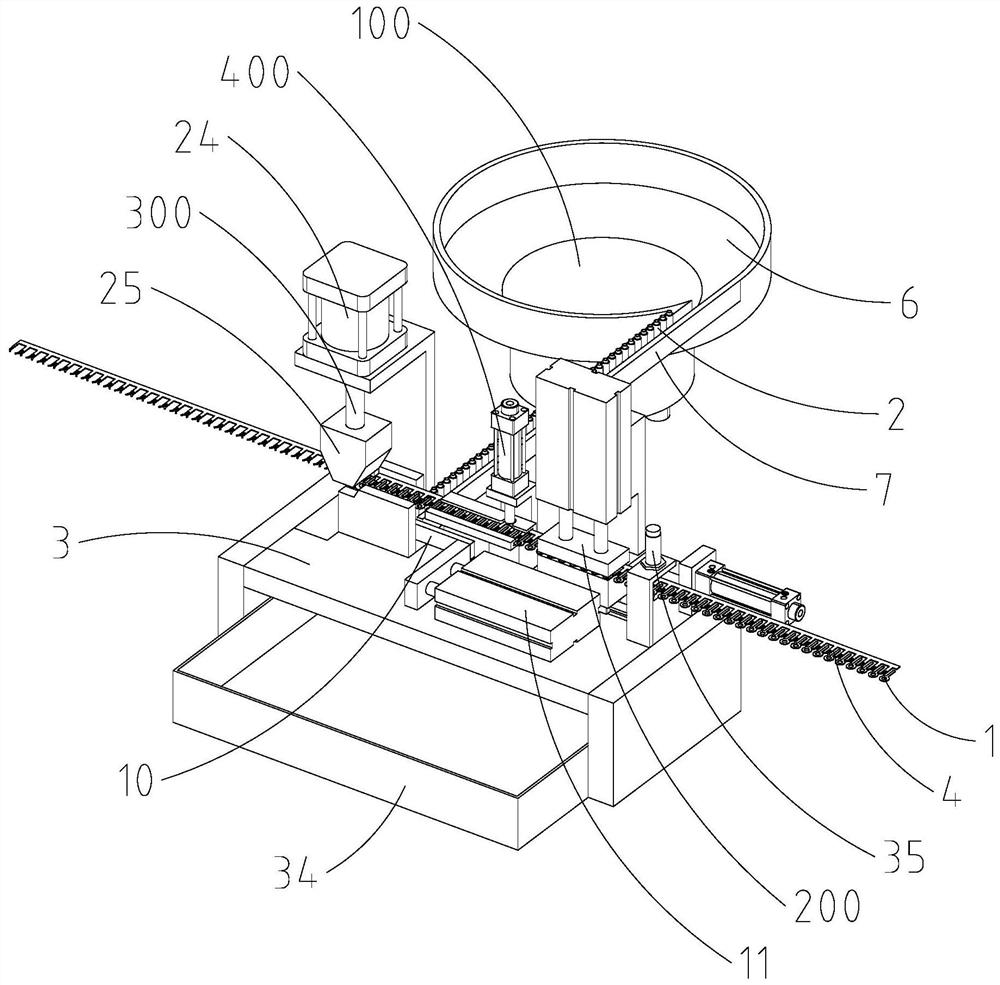
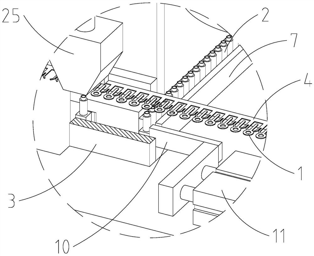
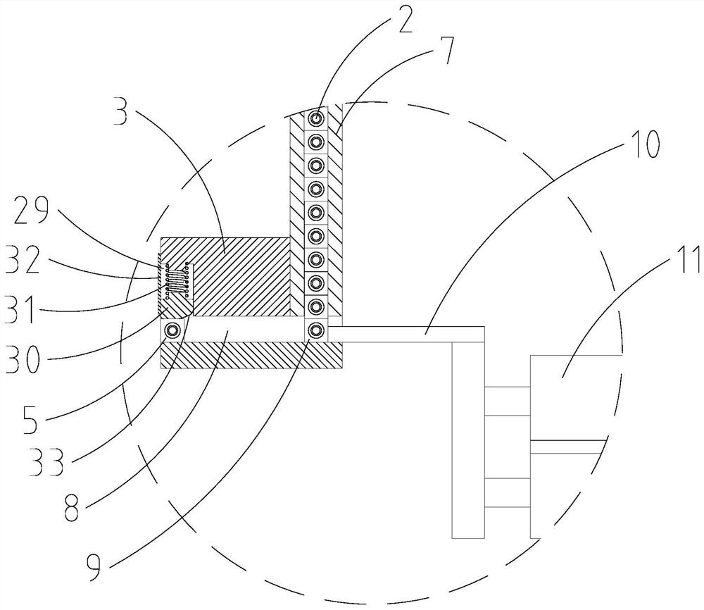
[0056] Such as Figure 1~8 As shown, a terminal riveting machine is used for riveting the tab 1 on the terminal 2, which includes a frame 3, a terminal feeding device 100, a tab conveying device 200 and a riveting device 300; wherein,

[0057] The tabs 1 are connected to the tab band 4 and arranged in sequence along the length direction of the tab band 4;

[0058] The frame 3 is provided with a terminal riveting station 5, a splice riveting station and a sheet passage suitable for the splice belt 4 to pass through;

[0059] The splicing conveying device 200 is connected to the frame 3, and is adapted to move the splicing belt 4 in the piece passage and send the splicing pieces 1 on the splicing belt 4 to the splicing belt 4 one by one. Tab riveti...


PUM


Abstract

The invention discloses a terminal riveting machine which is used for riveting connecting pieces on a terminal and comprises a rack, a terminal feeding device, a connecting piece conveying device and a rivet pressing device. Wherein the connecting pieces are connected to a connecting piece belt and are sequentially arranged in the length direction of the connecting piece belt; the rack is provided with a terminal riveting station, a connecting piece riveting station and a connecting piece channel suitable for the connecting piece belt to penetrate through. The connecting piece conveying device is suitable for acting to drive the connecting piece belt in the connecting piece channel to move and enable connecting pieces on the connecting piece belt to be conveyed to the connecting piece riveting station one by one; the terminal feeding device bears the terminals and is suitable for acting to convey the terminals to the terminal riveting station one by one; the rivet pressing device is suitable for acting to press and rivet the connecting pieces in the connecting piece riveting station on the terminal in the terminal riveting station and cut off the connecting piece from the connecting piece belt. The riveting efficiency can be improved, the labor cost is reduced, and the automation degree is improved.

Description

technical field [0001] The invention relates to a terminal riveting machine. Background technique [0002] At present, connection terminals are required for the connection between various components in electrical equipment, and riveting tabs are required on the connection terminals. However, when the existing riveting machine rivets the tabs on the terminal, workers need to manually load the material and operate the riveting machine for riveting, which has a low degree of automation, low production efficiency and high labor costs. Contents of the invention [0003] The technical problem to be solved by the present invention is to overcome the defects of the prior art and provide a terminal riveting machine, which can improve riveting efficiency, reduce labor cost and improve automation. [0004] In order to solve the above technical problems, the technical solution of the present invention is: a terminal riveting machine, which is used to rivet the tab on the terminal, wh...

Claims


Application Information

Patent Timeline
Patent Type & Authority Applications(China)
IPC IPC(8): H01R43/055H01R43/048
Inventor 孙其利
Owner 溧阳市华达电子电器厂
Learn More