Bus extension butt joint structure and GIS

A busbar and joint technology, applied in the field of busbar extension docking structure and GIS, can solve problems such as power outages in power stations

Pending Publication Date: 2021-04-20
HENAN PINGGAO ELECTRIC +1
View PDF4 Cites 0 Cited by
  • Summary
  • Abstract
  • Description
  • Claims
  • Application Information

AI Technical Summary

Problems solved by technology

[0004] The purpose of the present invention is to provide a busbar expansion docking structure to solve the technical problem of power outage in the power station during the busbar docking process in the middle and late expansion process of the prior art; the purpose of the present invention is also to provide a GIS

Method used


Image

  • Bus extension butt joint structure and GIS
  • Bus extension butt joint structure and GIS
  • Bus extension butt joint structure and GIS

Examples


Embodiment 1

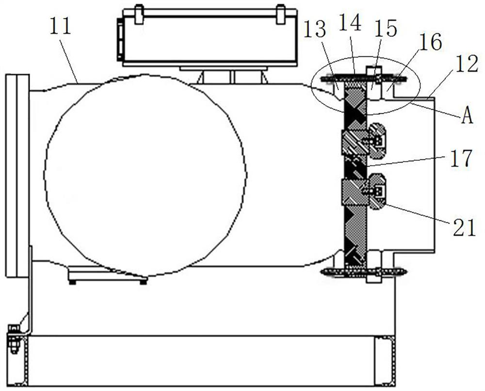
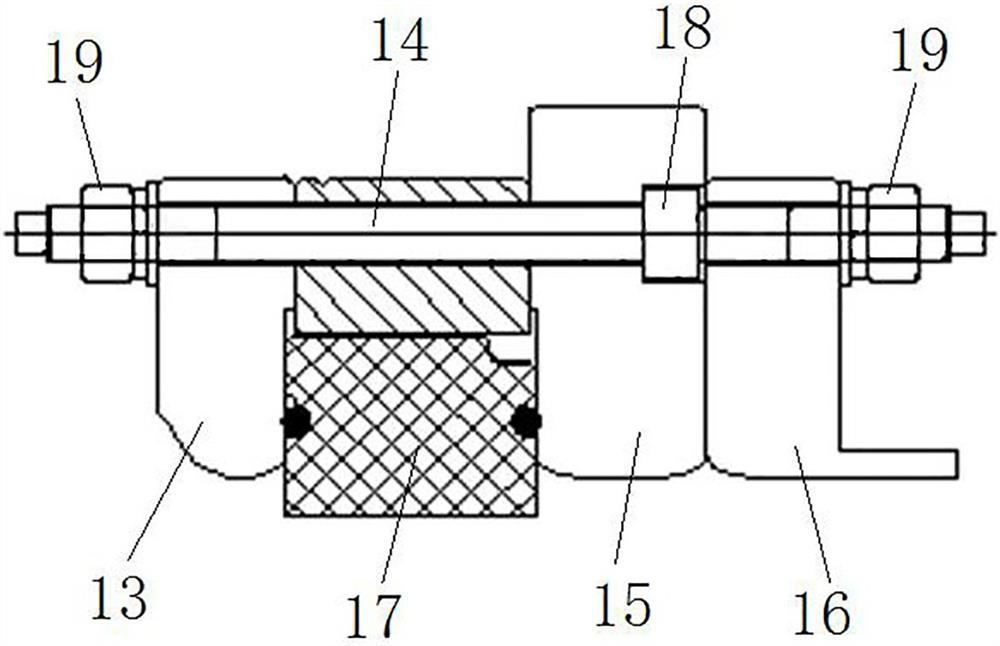
[0048] like figure 1 and figure 2 As shown, the GIS includes an isolation and grounding switch. The isolation and grounding switch includes a cylinder body 11, an insulator 17, a flange ring 15 and an end cap 12 are arranged in sequence on the right side of the cylinder body 11, and the cylinder body 11, the insulator 17, the flange ring 15 and the The end caps 12 are fixedly connected together by a screw 14 .

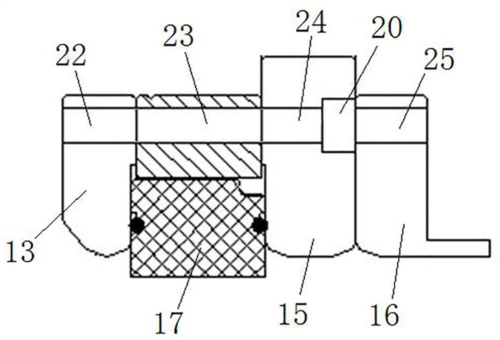
[0049] like figure 1 and image 3 As shown, the right end of the cylinder body 11 is provided with a first connecting flange 13, the first connecting flange 13 is provided with a plurality of first flange holes 22, the left end of the end cap 12 is provided with a second connecting flange 16, and The second connecting flange 16 is provided with a plurality of second flange holes 25 .

[0050] In this embodiment, the insulator 17 is arranged between the first connecting flange 13 and the second connecting flange 16, that is, between the cylinder body 11 and the end...

Embodiment 2

[0061] The difference between this embodiment and Embodiment 1 is that in Embodiment 1, the annular protrusion 18 and the screw 14 are integrally formed. In this embodiment, the annular protrusion is a nut, and the annular protrusion is threadedly connected to the screw rod.

Embodiment 3

[0063] The difference between this embodiment and Embodiment 1 is that in Embodiment 1, the position-limiting protrusion is an annular protrusion. In this embodiment, there are multiple limiting protrusions, and the limiting protrusions are arranged at intervals along the circumferential direction of the screw rod.


PUM


Abstract

The invention relates to a bus extension butt joint structure and a GIS. The bus extension butt joint structure comprises: a cylinder body which is provided with a first connecting flange, wherein the first connecting flange is provided with a first flange hole; an end cap provided with a second connecting flange, wherein a second flange hole is formed in the second connecting flange; an insulator arranged between the cylinder body and the end cap, wherein a fixing hole is formed in the edge of the insulator; a flange ring arranged between the insulator and the end cap, wherein a third flange hole is formed in the flange ring; and a screw rod, wherein fixing nuts are arranged at the two ends of the screw rod, and the screw rod penetrates through the first flange hole, the fixing hole, the third flange hole and the second flange hole so as to fixedly connect the cylinder body, the insulator, the flange ring and the end cap together. A limiting protruding part is arranged on the screw rod, a limiting groove is formed between the second connecting flange and the flange ring, the limiting groove is used for containing the limiting protruding part, and the limiting protruding part is matched with a fixing nut on the side of the cylinder body so that the cylinder body, the insulator and the flange ring can be independently fixed together.

Description

technical field [0001] The invention relates to a bus extension docking structure and a GIS. Background technique [0002] In recent years, as power grid users pay more and more attention to the safe operation of high-voltage switch products, combined electrical products are widely used in power systems due to their small footprint, small size, high reliability, and almost no maintenance. [0003] At present, most of the 110kV miniaturized GIS equipment adopts the structure of busbar three stations and busbar common air chamber. When the long-term project needs to be expanded, due to the safety hazard caused by air pressure, it is necessary to reduce the air pressure in the cylinder, and the reduction of air pressure will cause The insulation performance is reduced, so the power station needs to be cut off, and the power can only be transmitted after the docking is completed. This process takes a long time and causes inconvenience to the lives of the people. Contents of th...

Claims


Application Information

Patent Timeline
IPC IPC(8): H02B1/20H02B13/035
Inventor 李晓斌孙元元贺永明刘亮高博远齐小虎高玉莹吕宏伟张琳琳
Owner HENAN PINGGAO ELECTRIC
Why Eureka
Try Eureka