
Charging circuit, circuit control method and electronic equipment

A charging circuit, detection and control technology, applied to battery circuit devices, circuit devices, collectors, etc., can solve problems such as unfavorable miniaturization of electronic equipment

Active Publication Date: 2021-04-20
GUANGDONG OPPO MOBILE TELECOMM CORP LTD
View PDF5 Cites 2 Cited by
  • Summary
  • Abstract
  • Description
  • Claims
  • Application Information

AI Technical Summary

Problems solved by technology

However, setting a large number of various functions in electronic equipment is not conducive to the miniaturization of electronic equipment.

Method used


Image

  • Charging circuit, circuit control method and electronic equipment
  • Charging circuit, circuit control method and electronic equipment
  • Charging circuit, circuit control method and electronic equipment

Examples


Embodiment Construction

[0029] Example embodiments will now be described more fully with reference to the accompanying drawings. Example embodiments may, however, be embodied in many forms and should not be construed as limited to the embodiments set forth herein; rather, these embodiments are provided so that this disclosure will be thorough and complete, and will fully convey the concept of example embodiments to those skilled in the art. The same reference numerals denote the same or similar parts in the drawings, and thus their repeated descriptions will be omitted.

[0030] Furthermore, the described features, structures, or characteristics may be combined in any suitable manner in one or more embodiments. In the following description, numerous specific details are provided in order to give a thorough understanding of embodiments of the present disclosure. However, those skilled in the art will appreciate that the technical solutions of the present disclosure may be practiced without one or mo...


PUM


Abstract

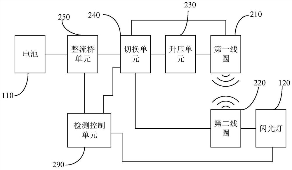
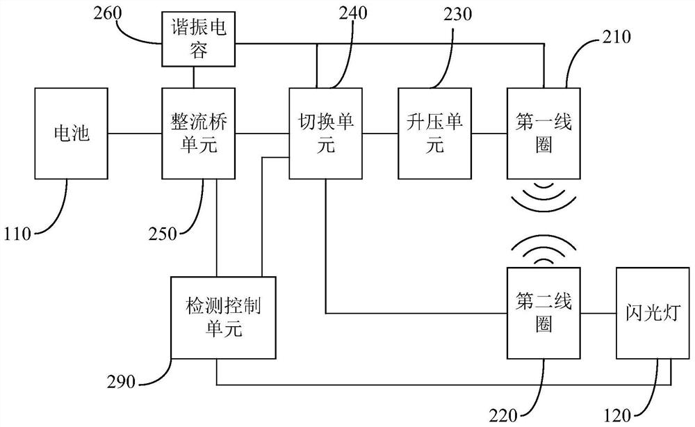
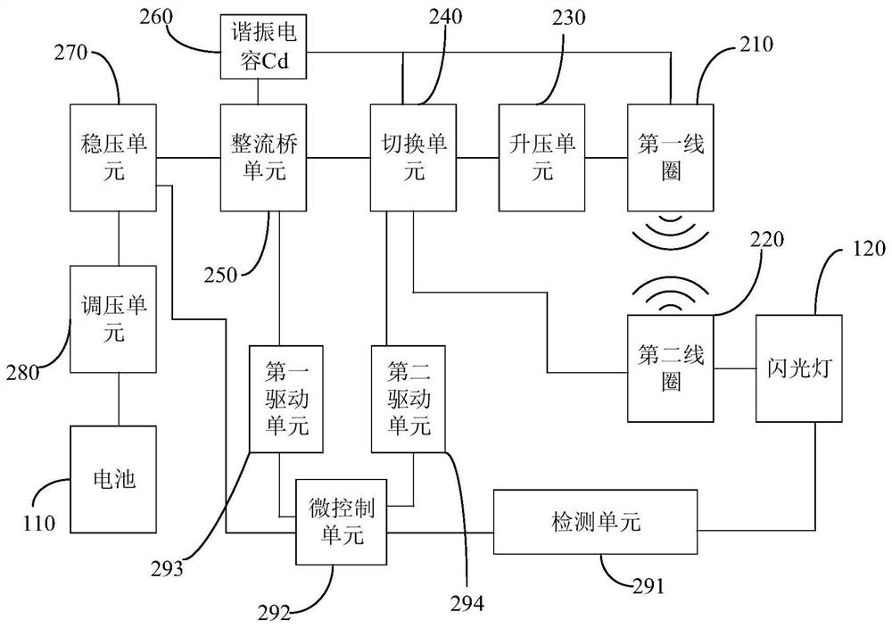
The invention relates to the technical field of electronic equipment, in particular to a charging circuit, a circuit control method and electronic equipment, the charging circuit has a charging mode and an excitation mode, the charging circuit is used for charging a battery in the charging mode, and the charging circuit is used for exciting a flash lamp in the excitation mode. The charging circuit comprises a first coil, a second coil, a boosting unit, a switching unit, a rectifier bridge unit and a detection control unit, the second coil is connected with the flash lamp and can be coupled with the first coil; the boosting unit is connected with the first coil; the switching unit is respectively connected with the first coil, the second coil and the boosting unit; the rectifier bridge unit is respectively connected with the switching unit and the battery, and the detection control unit is respectively connected with the flash lamp, the switching unit and the rectifier bridge unit. The number of devices in the electronic equipment can be reduced, and lightening and thinning of the electronic equipment are facilitated.

Description

technical field [0001] The present disclosure relates to the technical field of electronic equipment, and in particular, to a charging circuit, a circuit control method, and electronic equipment. Background technique [0002] With the development and progress of technology, people have higher and higher functional requirements for mobile communication electronic equipment such as mobile phones. In order to meet this demand, electronic equipment often needs to integrate a large number of various functional devices to achieve richer functions. However, setting a large number of various functional devices inside electronic equipment is not conducive to the miniaturization of electronic equipment. [0003] It should be noted that the information disclosed in the above background section is only for enhancing the understanding of the background of the present disclosure, and therefore may include information that does not constitute the prior art known to those of ordinary skill ...

Claims


Application Information

Patent Timeline
IPC IPC(8): H02J7/00H02J7/02H02J50/10H02J50/12H05B41/282H05B41/30
Inventor 郑毅成
Owner GUANGDONG OPPO MOBILE TELECOMM CORP LTD
Learn More