
Environment-friendly sewage discharge sedimentation tank

A settling tank and environmental protection technology, applied in the field of settling tanks, can solve the problems such as difficult flow of impurities, unclean discharge of impurities, troublesome manual salvage, etc., and achieve the effect of easy to drive the discharge of impurities, convenient for operators, and simple structure

Inactive Publication Date: 2021-04-23
张俊杰
View PDF5 Cites 1 Cited by
  • Summary
  • Abstract
  • Description
  • Claims
  • Application Information

AI Technical Summary

Problems solved by technology

[0003] After the impurities at the bottom of the existing sedimentation tank have accumulated to a certain extent, they need to be discharged to prevent the impurities from remaining at the bottom of the sedimentation tank for a long time and will affect the purified water quality. However, the existing sewage discharge method of the sedimentation tank is to open a At the sewage outlet, the water flow drives the miscellaneous sewage to be discharged. However, due to the high flow velocity near the sewage outlet, the miscellaneous sewage in the area near the sewage outlet will be basically discharged, and the area far from the sewage outlet, especially the miscellaneous at the bottom of the sedimentation tank. Near the sewage, the water flow velocity is very small, and it is not easy to drive the large sewage to flow, resulting in the area far from the sewage outlet, the sewage is not clean, and manual salvage is more troublesome, and the long-term existence of the sewage at the bottom will cause impact on water quality

Method used


Image

  • Environment-friendly sewage discharge sedimentation tank
  • Environment-friendly sewage discharge sedimentation tank
  • Environment-friendly sewage discharge sedimentation tank

Examples


Embodiment Construction

[0027] The following will clearly and completely describe the technical solutions in the embodiments of the present invention with reference to the accompanying drawings in the embodiments of the present invention. Obviously, the described embodiments are only some, not all, embodiments of the present invention. Based on the embodiments of the present invention, all other embodiments obtained by persons of ordinary skill in the art without making creative efforts belong to the protection scope of the present invention.

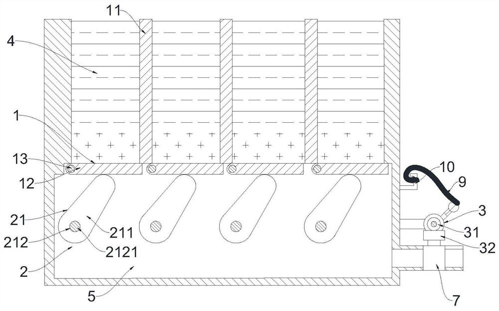
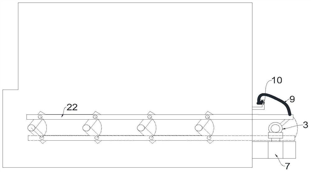
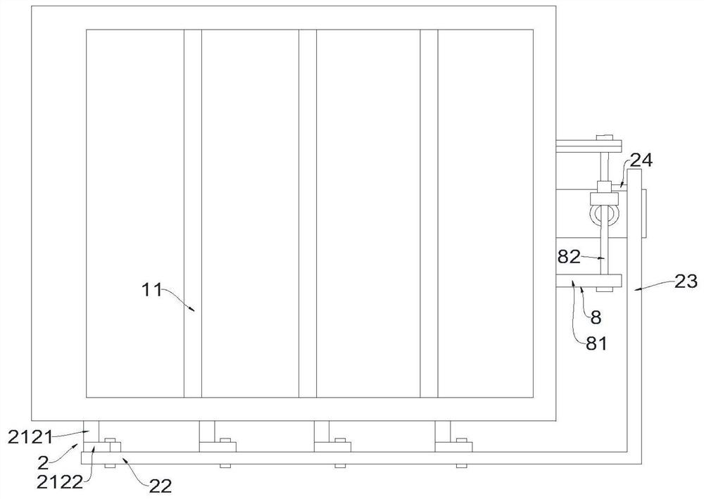
[0028] see Figure 1-5 An environmentally friendly sewage sedimentation tank, including a sedimentation structure 1, a rotating sewage structure 2, a transmission structure 3, a fixed structure 8 and a main body of the sedimentation tank. The main body of the sedimentation tank has a sedimentation area 4 and a sewage area 5, and the sedimentation area 4 is located in the sewage area 5 The lower side, and the sedimentation zone 4 and the sewage discharge zone 5...


PUM


Abstract

The invention belongs to the field of sedimentation tanks, and relates to an environment-friendly sewage discharge sedimentation tank, which comprises a sedimentation structure, a rotary sewage discharge structure, a transmission structure, a fixing structure and a sedimentation tank body. The sedimentation tank body has a sedimentation zone and a sewage discharge zone, and the sedimentation structure is arranged in the sedimentation zone. The rotary sewage discharge structure is rotatably connected to the front and rear side walls of the sedimentation tank. The fixing structure is fixedly connected to the right side wall of the sedimentation tank body. The transmission structure is connected to the fixing structure. a sewage discharge opening is formed in the right end of the lower portion of the sedimentation tank body, a sewage discharge pipe is connected to the sewage discharge opening, and a sewage discharge valve is installed on the sewage discharge pipe. The sedimentation structure is used for sedimentation of contaminants. The rotary sewage discharge structure is used for controlling opening of the bottom of the sedimentation structure. The rotary sewage discharge structure is linked with the sewage discharge valve through the transmission structure. The sewage discharge zone is arranged below the sedimentation tank body, a sedimentation plate is turned over while the sewage discharge valve is opened, contaminants are taken away by water flow while falling into the sewage discharge zone, and the sedimentation tank is simple, convenient and complete in sewage discharge.

Description

technical field [0001] The invention belongs to the field of settling tanks, in particular to an environment-friendly sewage settling tank. Background technique [0002] Sedimentation tank is a structure that uses sedimentation to remove suspended solids in water and is an equipment for purifying water quality. Use the natural precipitation of water or the effect of coagulation and sedimentation to remove suspended solids in water. [0003] After the impurities at the bottom of the existing sedimentation tank have accumulated to a certain extent, they need to be discharged to prevent the impurities from remaining at the bottom of the sedimentation tank for a long time and will affect the purified water quality. However, the existing sewage discharge method of the sedimentation tank is to open a At the sewage outlet, the water flow drives the miscellaneous sewage to be discharged. However, due to the high flow velocity near the sewage outlet, the miscellaneous sewage in the ...

Claims


Application Information

Patent Timeline
Patent Type & Authority Applications(China)
IPC IPC(8): B01D21/02B01D21/24
Inventor 张俊杰
Owner 张俊杰
Learn More