Automatic pushing and bending die of common punch press

A technology of bending dies and punching machines, which is applied in the direction of manufacturing tools, vibration suppression adjustment, feeding devices, etc. It can solve problems such as difficulty in handling, low efficiency, and risk of work-related injuries, and achieves avoiding rigid collisions, improving work efficiency, and good buffering effect Effect

Inactive Publication Date: 2021-04-23
苏州市富通精密机械有限公司
View PDF6 Cites 1 Cited by
  • Summary
  • Abstract
  • Description
  • Claims
  • Application Information

AI Technical Summary

Problems solved by technology

[0004] For this reason, the embodiment of the present invention provides an automatic pushing and bending mold for ordinary punching machines, which facilitates the workpiece to be transported to the top of the V-groove of the lower mold through an automatic conveying mechanism, avoiding manual contact with the V-groove of the upper mold and the lower mold, which will be safer, and It can achieve continuous work and improve work efficiency. The buffer mechanism can play a good buffer role when processing workpieces to avoid damage to the upper and lower dies, so as to solve the problem in the prior art that most bending dies are suitable for Conventional sheet metal parts processing requires manual placement of the sheet metal parts at the processing position. As a result, for the processing of small sheet metal parts, the same method of manually placing the sheet metal parts is used. If the hand is too close to the station, there will be The risk of work-related injuries and the low efficiency caused by difficult handling, and the buffer structure between the upper mold and the lower mold is not perfect, and the upper mold and the lower mold are easily damaged.

Method used


Image

  • Automatic pushing and bending die of common punch press
  • Automatic pushing and bending die of common punch press
  • Automatic pushing and bending die of common punch press

Examples


Embodiment Construction

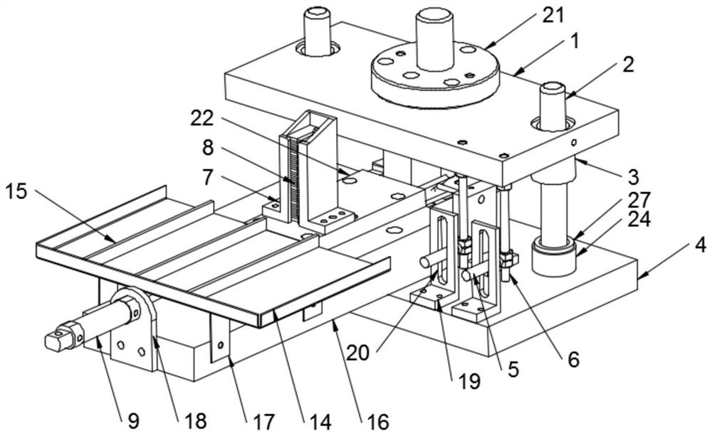
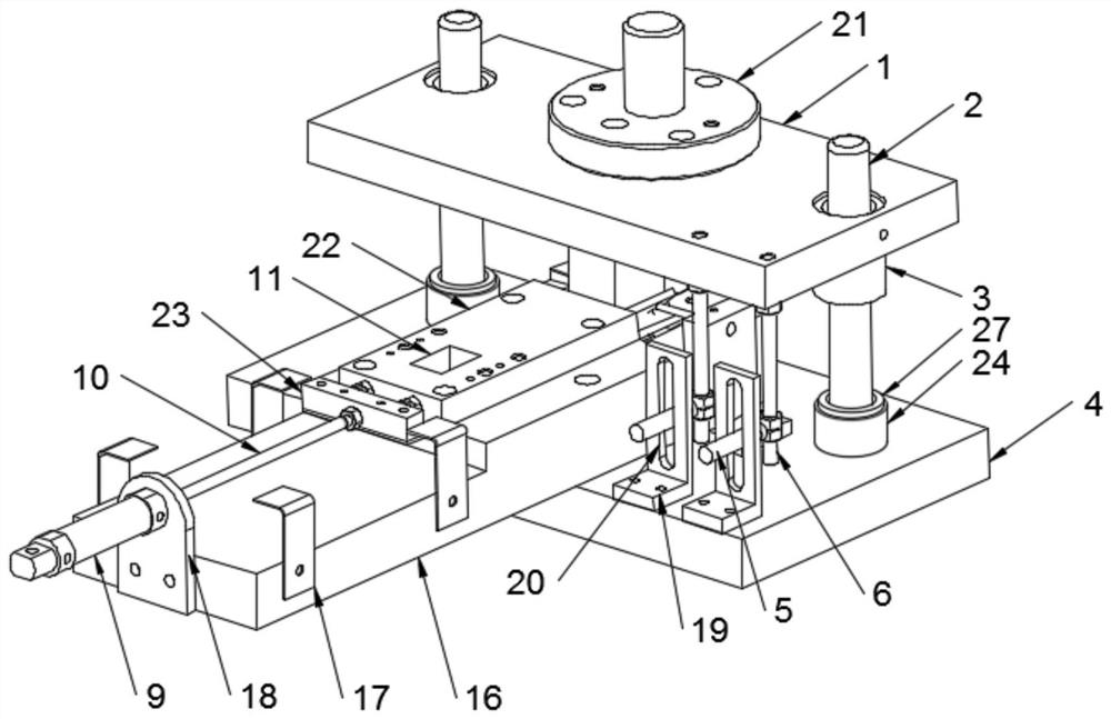
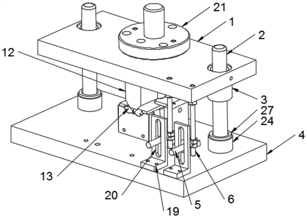
[0028] The implementation mode of the present invention is illustrated by specific specific examples below, and those who are familiar with this technology can easily understand other advantages and effects of the present invention from the contents disclosed in this description. Obviously, the described embodiments are a part of the present invention. , but not all examples. Based on the embodiments of the present invention, all other embodiments obtained by persons of ordinary skill in the art without making creative efforts belong to the protection scope of the present invention.

[0029] Refer to the attached Figure 1-7 , a kind of ordinary punching machine automatic pushing material bending mold of this embodiment, comprises and comprises upper mold base 1 and lower mold base 4, and described upper mold base 1 is arranged on the top of lower mold base 4, and the top of described lower mold base 4 is fixedly arranged There is a fixed base 16, the top of the fixed base 16...


PUM


Abstract

The invention discloses an automatic pushing and bending die of a common punch press. The die comprises an upper die holder and a lower die holder, wherein a fixed base is fixedly arranged at the top end of the lower die holder, and an automatic conveying mechanism is arranged at the top end of the fixed base; the automatic conveying mechanism comprises a fixing plate, a linear air cylinder is fixedly arranged at the front end of the fixing plate, an air cylinder telescopic rod is fixedly arranged at the movable end of the linear air cylinder, a protection plate is fixedly arranged at the top end of the fixed base, a machining station is arranged on the protection plate, a product clamping bin is fixedly arranged at the top end of the protection plate, and a product placing groove is formed in the product clamping bin. According to the die, a workpiece is conveniently conveyed to the top end of a lower-die V-shaped groove through the automatic conveying mechanism, manual contact with an upper die and the lower-die V-shaped groove is avoided, higher safety is achieved, continuous work can be achieved, the working efficiency is improved, a good buffering effect can be achieved through a buffering mechanism when the workpiece is machined, and damage to the upper die and a lower die is avoided.

Description

technical field [0001] The embodiment of the present invention relates to the technical field of moulds, in particular to an automatic pushing and bending die for a common punch press. Background technique [0002] Conventional sheet metal parts in the factory, especially large ones, are processed on CNC bending machines. Under the pressure of the upper or lower dies of the bending machine, the sheet metal parts first undergo elastic deformation and then enter plastic deformation. In the initial stage of plastic bending, The sheet metal part is free to bend. With the pressure of the upper die or the lower die on the sheet metal, the sheet metal part and the inner surface of the V-shaped groove of the lower die are gradually tightened, and the radius of curvature and the bending arm are also gradually reduced. Continue Pressurize until the stroke ends, so that the upper and lower molds are in close contact with the plate at three points. At this time, a V-shaped bending is co...

Claims


Application Information

Patent Timeline
Patent Type & Authority Applications(China)
IPC IPC(8): B21D5/01B21D43/24B21D43/02B21D43/00B21C51/00F16F15/067
CPCB21D5/01B21D43/24B21D43/027B21D43/003B21C51/00F16F15/067
Inventor 沈力
Owner 苏州市富通精密机械有限公司
Why Eureka
Try Eureka