Automatic riveting device for mechanical arm manufacturing

A technology of mechanical arm and driving device, which is applied in the direction of manufacturing tools, metal processing equipment, forming tools, etc. It can solve the problems of mold offset, lack of automation, lack of cooling function, etc., and achieve the effect of prolonging the service life and preventing damage

Inactive Publication Date: 2021-04-23
郑克锋
View PDF0 Cites 1 Cited by
  • Summary
  • Abstract
  • Description
  • Claims
  • Application Information

AI Technical Summary

Problems solved by technology

[0004] The purpose of the present invention is to provide an automatic riveting device for manipulator arm manufacturing, which solves the existing problems of insufficient automation, easy deviation of the mold when the punching machine is working, and lack of cooling function

Method used


Image

  • Automatic riveting device for mechanical arm manufacturing
  • Automatic riveting device for mechanical arm manufacturing
  • Automatic riveting device for mechanical arm manufacturing

Examples


Embodiment 1

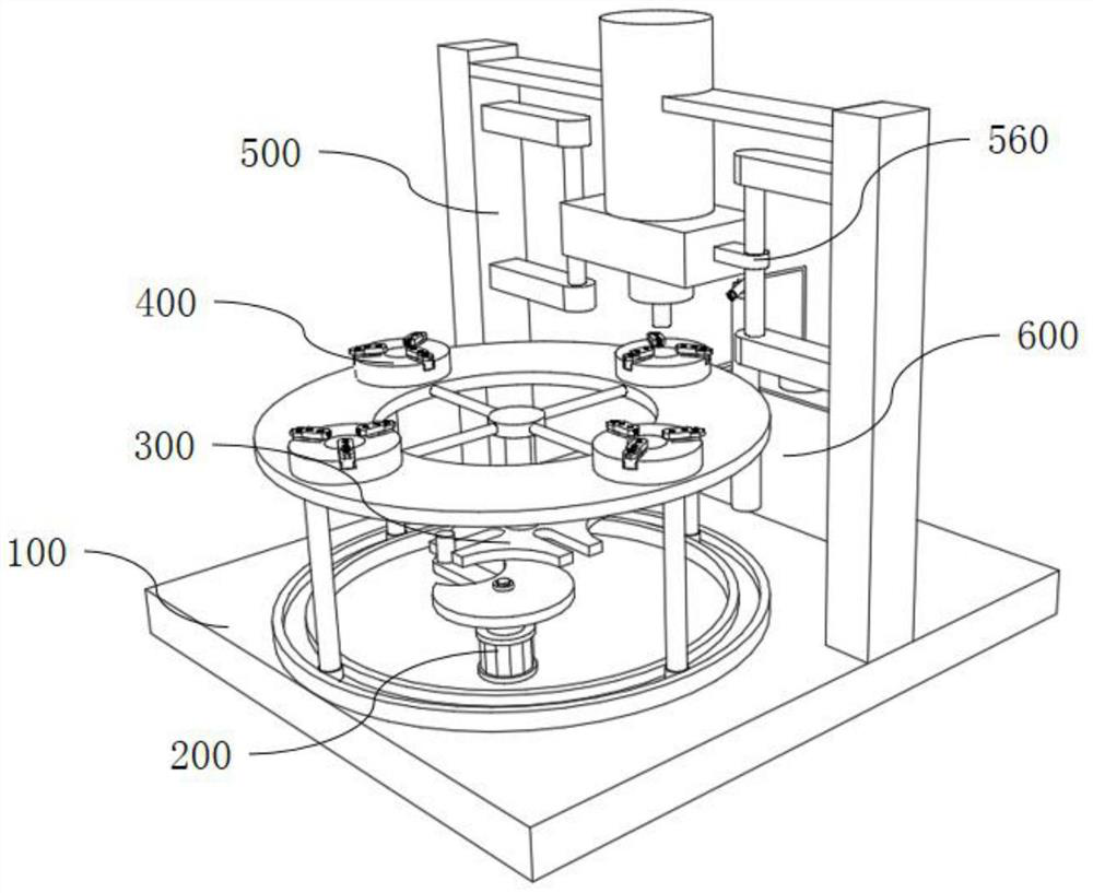
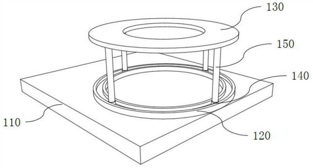
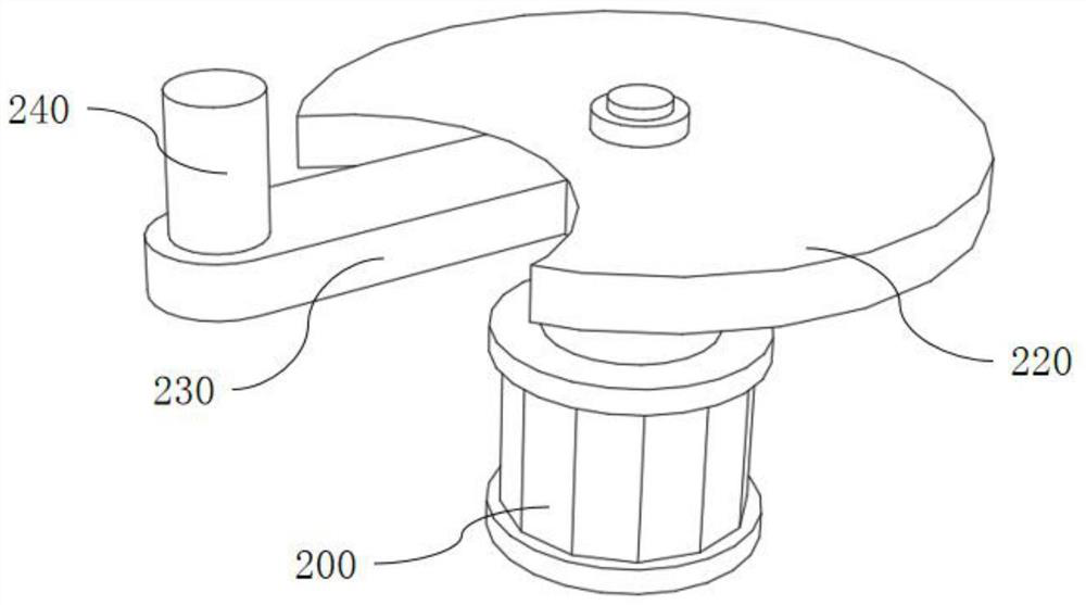
[0032] see Figure 1-7 As shown, the present invention is an automatic riveting device for manipulator manufacturing, including a base 100, a driving device 200, a rhythmic rotating device 300, a triangular chuck 400, a stamping device 500 and a cooling device 600, and the base 100 includes a bottom plate 110 and a reinforcement plate 130, the driving device 200 includes a driving motor 210 and a guide post 240, the lower surface of the driving motor 210 is welded to the upper surface of the bottom plate 110, the rhythm rotating device 300 includes a rotating seat 310, a fixed rod 340 and a rotating plate 350, and the upper surface of the rotating plate 350 is provided with There are several grooves, the guide column 240 is slidingly matched with several grooves, the lower surface of the rotating base 310 is welded to the upper surface of the bottom plate 110, one end of several fixed rods 340 is welded to the inner surface of the reinforcement plate 130, and the triangular chu...

Embodiment 2

[0041] see Figure 1-7 As shown in the present invention, by setting the driving device 200 and the rhythmic rotating device 300, the rotating plate 350 can be slotted according to the needs, and the size of the rotating plate 220 can be adjusted at the same time to adapt to the number of slots, and the guide column 240 can be slidably matched with the groove. To realize the rhythmic and regular rotation of the rotating rod 320, the number of triangular chucks should be consistent with the number of slots. By setting the triangular chuck 400 and the stamping device 500, the triangular chuck 400 is used to clamp the column device, and then The stamping device 500 can be used to carry out regular stamping. The working frequency of the stamping machine 520 should be adapted to the number of the triangular chucks 400, so as to achieve the purpose of automatic riveting and more automation. By setting the cooling device 600, the stamping is completed. Finally, since the stamping par...


PUM


Abstract

The invention discloses an automatic riveting device for mechanical arm manufacturing, and relates to the technical field of mechanical arm manufacturing. The automatic riveting device for mechanical arm manufacturing comprises a base, a driving device, a rhythm rotating device, triangular chucks, a stamping device and a cooling device; a guide column is in sliding fit with a plurality of grooves; the lower surface of a rotating base is welded to the upper surface of a bottom plate; the lower surfaces of two supporting columns are connected with the upper surface of the bottom plate; the lower surface of a water tank is connected with the upper surface of the bottom plate; and the lower surface of a supporting rod is connected with the upper surface of the bottom plate. The driving device and the rhythm rotating device are arranged, and the guide column is in sliding fit with the grooves to achieve rhythmic and regular rotation of a rotating rod; the triangular chucks and the punching device are arranged, the triangular chucks are used for clamping a workpiece, the working frequency of a stamping machine should be matched with the number of the triangular chucks so that the purpose of automatic riveting can be achieved, and the degree of automation is higher; and the cooling device is arranged, and continuously sprays water for cooling, so that damage caused by overheating is prevented, and the service life of the device is prolonged.

Description

technical field [0001] The invention belongs to the technical field of manipulator arm manufacture, and in particular relates to an automatic riveting device for manipulator arm manufacture. Background technique [0002] Robotic arm, also called manipulator, refers to a complex system with high precision, multiple input and multiple output, high nonlinearity, and strong coupling. It has unique operational flexibility and can replace human hands for dangerous operations. Therefore, it has been assembled in industry and is safe and explosion-proof. The robotic arm is a complex system with uncertainties such as parameter perturbation, external interference, and unmodeled dynamics. Because the robotic arm requires a variety of complex and diverse operations and movements when in use, the mechanical arm During manufacturing, a riveting device is used to rivet the parts. Automatic riveting is fast, convenient and efficient in the process of part generation. [0003] The automatic...

Claims


Application Information

Patent Timeline
IPC IPC(8): B21D39/00B21D37/16B21D37/14
CPCB21D37/14B21D37/16B21D39/00
Inventor 郑克锋李伟铭李丽君
Owner 郑克锋
Why Eureka
Try Eureka