Transfer device for machining

A transfer device and mechanical processing technology, applied in the field of mechanical processing, can solve problems such as difficult promotion and application, scratches and collisions of parts, and inability to classify and place

Pending Publication Date: 2021-04-23
舒德祥
View PDF7 Cites 0 Cited by
  • Summary
  • Abstract
  • Description
  • Claims
  • Application Information

AI Technical Summary

Problems solved by technology

[0003] The mechanical parts need to be transferred during the machining process. Although the current transfer device for mechanical processing can transfer the parts, the parts are piled up during the transfer process, and there will be scratches and collisions between the parts inside the transfer device, which will affect the quality of the parts. Appearance and use effect cannot meet the needs of processing. It can be seen from the above that the existing transfer devices for mechanical processing have the disadvantage of not being able to be classified and placed, and it is difficult to be popularized and applied.

Method used


Image

  • Transfer device for machining
  • Transfer device for machining
  • Transfer device for machining

Examples


Embodiment 1

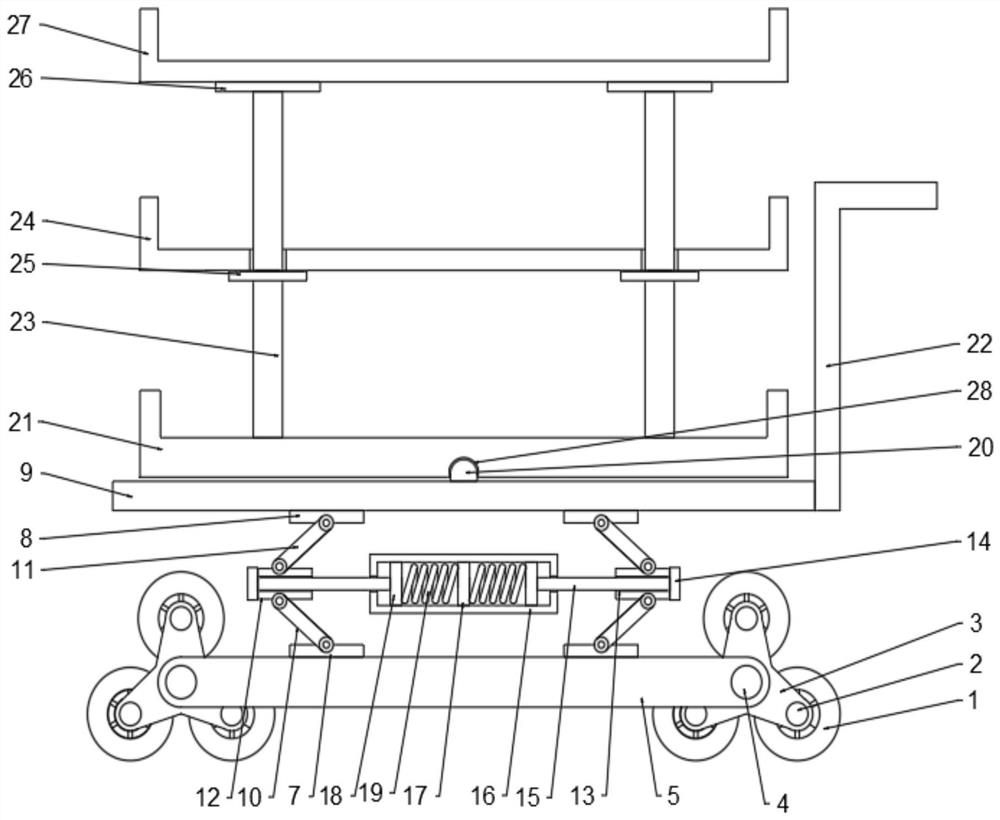
[0025] see Figure 1 ~ Figure 3 , a transfer device for mechanical processing, comprising a support plate 9, a shock absorbing assembly is provided at the bottom of the support plate 9, a moving assembly is fixedly connected to the bottom of the shock absorbing assembly, and a first placement plate is provided above the support plate 9 21. A central rotating rod 20 is fixedly arranged at the center above the support plate 9, and a rotating hole 28 cooperating with the central rotating rod 20 is provided at the bottom of the first placing plate 21. There is a support rod 23, the middle part of the support rod 23 is provided with a second baffle plate 25, the outside of the support rod 23 above the second baffle plate 25 is provided with a second placement plate 24, and the top of the support rod 23 is fixedly connected with Top plate 26, the third placement plate 27 is fixedly connected above the top plate 26, through the first placement plate 21, the second placement plate 24 ...

Embodiment 2

[0031] see Figure 1 ~ Figure 4 , such as a transfer device for mechanical processing in Example 1, including a support plate 9, the bottom of the support plate 9 is provided with a shock absorbing assembly, the bottom of the shock absorbing assembly is fixedly connected with a moving assembly, and the top of the support plate 9 A first placing plate 21 is provided, and a central rotating rod 20 is fixedly arranged at the center above the support plate 9, and a rotating hole 28 cooperating with the central rotating rod 20 is provided at the bottom of the first placing plate 21, and the first placing The top of the plate 21 is symmetrically and vertically provided with a support rod 23, the middle part of the support rod 23 is provided with a second baffle plate 25, and the outside of the support rod 23 above the second baffle plate 25 is provided with a second placement plate 24. The top of the rod 23 is fixedly connected with a top plate 26, and the top of the top plate 26 is...


PUM


Abstract

The invention discloses a transfer device for machining, which belongs to the technical field of machining and solves the problem that an existing transfer device for machining cannot be placed in a classified mode. The transfer device for machining is characterized by comprising a supporting plate, wherein a damping assembly is arranged at the bottom of the supporting plate, and a moving assembly is fixedly connected to the bottom of the damping assembly; a first placing plate is arranged above the supporting plate, supporting rods are symmetrically and vertically arranged above the first placing plate, second baffle plates are arranged in the middles of the supporting rods, a second placing plate is arranged on the outer sides of the supporting rods above the second baffle plates, a top plate is fixedly connected to the tops of the supporting rods, and a third placing plate is fixedly connected to the upper portion of the top plate. Parts are placed in a layered mode through the first placing plate, the second placing plate and the third placing plate, obstacles are conveniently crossed through the moving assembly, vibration borne by the device is weakened through the damping assembly, and thus, the transfer device has the advantages of being placed in a layered mode, flexible to move, effective in damping, simple, convenient to use and practical.

Description

technical field [0001] The invention relates to the technical field of mechanical processing, in particular to a transfer device for mechanical processing. Background technique [0002] Machining refers to the process of changing the shape or performance of a workpiece through a mechanical device. According to the difference in processing methods, machining can be divided into cutting processing and pressure processing. In the production process, the process of changing the shape, size, position and nature of the production object to make it a finished or semi-finished product is called a process. It is an essential part of the production process. The process can be divided into casting, forging, stamping, welding, machining and assembly processes. The mechanical manufacturing process generally refers to the sum of the machining process of parts and the assembly process of machines. Other processes are called auxiliary processes. Processes such as transportation, storage,...

Claims


Application Information

Patent Timeline
Patent Type & Authority Applications(China)
IPC IPC(8): B25H5/00B25H3/00F16F15/06
CPCB25H5/00B25H3/00F16F15/06
Inventor 舒德祥
Owner 舒德祥
Why Eureka
Try Eureka