Automatic billiard placing robot capable of identifying billiard numbers
What is AI technical title?
AI technical title is built by PatSnap AI team. It summarizes the technical point description of the patent document.
A technology of robots and billiards, applied in the field of billiards recognition, can solve the problems of wasting time, large expenses, and non-standard artificial swinging positions.
Active Publication Date: 2021-04-23
深圳市瑞驰文体科技发展有限公司
View PDF6 Cites 1 Cited by
Summary
Abstract
Description
Claims
Application Information
AI Technical Summary
This helps you quickly interpret patents by identifying the three key elements:
Problems solved by technology
Method used
Benefits of technology
Problems solved by technology
[0003] The present invention provides an automatic swinging robot capable of identifying billiard ball numbers, which is used to solve the situation that the position of the manual swinging ball is not standard through manual identification, wasting time, wasting manpower, and costing a lot
Method used
Image
Click on the blue label to locate the original text in one second.
Reading with bidirectional positioning of images and text.
Examples
Embodiment 1
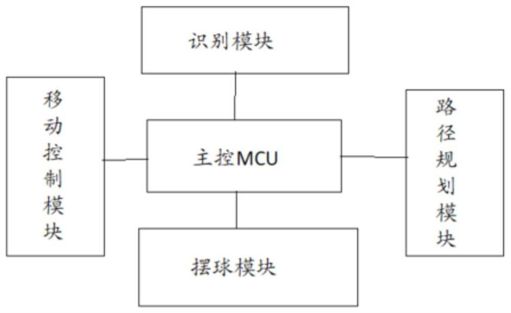
[0072] as attached figure 1 As shown, the present invention is a kind of automatic ball swinging robot capable of identifying billiard ball numbers, which includes:
[0073] Recognition module: used to take high-definition pictures on the billiard table and identify the number of each billiard ball in the high-definition pictures;
[0074] Swing ball module: used to place billiard balls on the billiard table according to receiving swing ball instructions; among them,
[0075] The swinging ball instruction includes a real-time user input instruction and a default swinging ball instruction;
[0076] Mobile control module: used to control the movement and movement direction of the swing ball device; wherein,
[0077] The direction of movement includes front-back direction, left-right direction and up-down direction;
[0078] Path planning module: used to generate a swing ball path planning instruction according to the high-definition picture and the swing ball instruction, and...
Embodiment 2
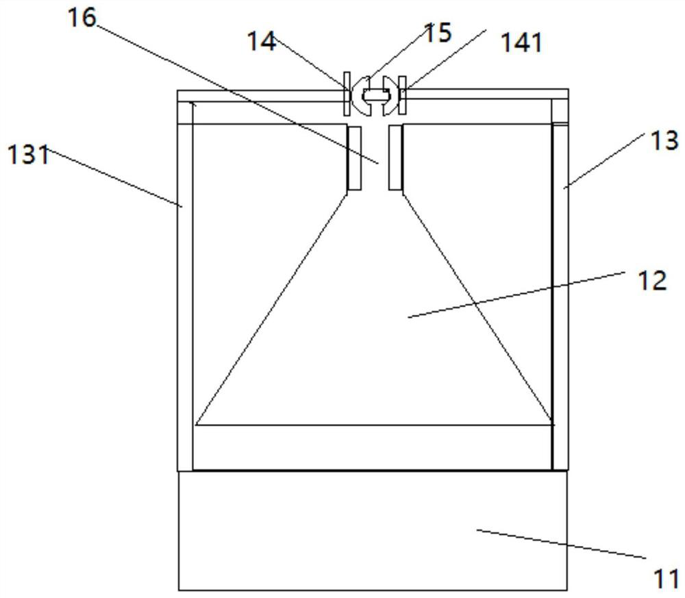
[0083] As an embodiment of the present invention: the recognition device includes a recognition processor, a storage device and an image acquisition device, and the image acquisition device and the storage device are electrically connected to the recognition processor; wherein
[0084] The image acquisition device includes a first camera unit and a second camera unit; wherein,
[0085] The first camera unit is used to take high-definition pictures of the entire billiard table top; and is used to determine the high-definition pictures of the billiard table top.
[0086] The second camera unit is used to single-identify the billiard ball directly below when the recognition device moves to the upper part of any billiard ball on the billiard table, and obtain a single picture of the billiard ball; Accurate identification.
[0087] The first camera unit is a dot matrix camera, and the second camera unit is a small viewing angle high-definition camera;
[0088] The storage device ...
PUM
Abstract
The invention provides an automatic billiard placing robot capable of identifying billiard numbers. The automatic billiard placing robot comprises an identification module, a billiard placing module, a moving control module, a path planning module and a main control MCU, wherein the identification module is used for shooting high-definition pictures on a billiard table and identifying the number of each billiard in the high-definition pictures; the billiard placing module is used for placing the billiards on the billiard table according to a received billiard placing instruction; the billiard placing instruction comprises a user real-time input instruction and a default billiard placing instruction; the moving control module is used for controlling the movement and the movement direction of a billiard placing device; the movement direction comprises a front-back direction, a left-right direction and an up-down direction; the path planning module is used for generating a billiard placing path planning instruction according to the high-definition pictures and the billiard placing instruction and sending the billiard placing path planning instruction to the billiard placing module and the moving control module; and the main control MCU is used for controlling the identification module, the billiard placing module, the moving control module and the path planning module to carry out automatic billiard placing.
Description
technical field [0001] The invention relates to the technical field of billiard ball recognition, in particular to an automatic swinging ball robot capable of recognizing billiard ball numbers. Background technique [0002] At present, when the billiard balls on the market are generally placed, they are placed manually, and there are non-standard situations in artificially placed balls. The colored balls are arranged in a triangle, the No. 8 ball is placed in the middle of the third row, and the remaining panchromatic and suit balls should be placed as far apart as possible. The first ball on the vertex is placed on the point where the ball is placed, and the balls must be placed squarely close to each other without any gaps. The cue ball (ball in hand) is placed in the kick-off area on the other side of the table. And the form of snooker before the start. When placing it manually, because the human vision cannot be compared with that of the machine, there is whether the ...
Claims
Application Information
Patent Timeline
Application Date:The date an application was filed.
Publication Date:The date a patent or application was officially published.
First Publication Date:The earliest publication date of a patent with the same application number.
Issue Date:Publication date of the patent grant document.
PCT Entry Date:The Entry date of PCT National Phase.
Estimated Expiry Date:The statutory expiry date of a patent right according to the Patent Law, and it is the longest term of protection that the patent right can achieve without the termination of the patent right due to other reasons(Term extension factor has been taken into account ).
Invalid Date:Actual expiry date is based on effective date or publication date of legal transaction data of invalid patent.

