
Method and device for calculating engine response time

A response time and engine technology, applied in combustion engine, engine control, machine/engine, etc., can solve problems such as inaccurate calculation of system response time, achieve the effect of maintaining engine output and reducing fuel consumption

Active Publication Date: 2022-03-29
GREAT WALL MOTOR CO LTD
View PDF15 Cites 0 Cited by
  • Summary
  • Abstract
  • Description
  • Claims
  • Application Information

AI Technical Summary

Problems solved by technology

[0005] In view of this, the present invention aims to propose a method and device for calculating the engine response time to solve the problem in the prior art that the system response time cannot be accurately calculated during the torque switching process of the random cylinder deactivation engine of the automobile

Method used


Image

  • Method and device for calculating engine response time
  • Method and device for calculating engine response time
  • Method and device for calculating engine response time

Examples


Embodiment Construction

[0053] It should be noted that, in the case of no conflict, the embodiments of the present invention and the features in the embodiments can be combined with each other.

[0054] The present invention will be described in detail below with reference to the accompanying drawings and examples.

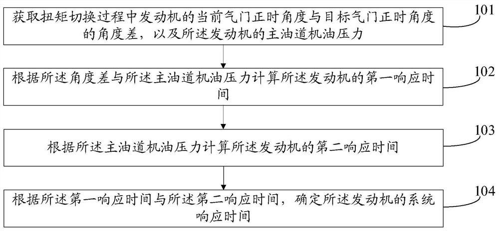
[0055] Such as figure 1 As shown, it shows a flow chart of steps of a method for calculating engine response time provided by an embodiment of the present invention, as shown in figure 1 As shown, the method may include:

[0056] Step 101: Obtain the angle difference between the current valve timing angle of the engine and the target valve timing angle during the torque switching process, and the main oil passage oil pressure of the engine.

[0057]In practical application, when driving a car, the driver can change the opening of the accelerator pedal by stepping on it to change the torque of the current engine. When the engine demand torque changes, it can be considered that the engi...


PUM


Abstract

The present invention provides a method and device for calculating engine response time, which are applied in the field of engine cylinder deactivation control. The method may include obtaining the angle difference between the current valve timing angle of the engine and the target valve timing angle during the torque switching process, and The oil pressure of the main oil gallery of the engine; the first response time of the engine is calculated according to the angle difference and the oil pressure of the main oil gallery; the second response time of the engine is calculated according to the oil pressure of the main oil gallery ; Determine the system response time of the engine according to the first response time and the second response time. Through the solutions provided by the embodiments of the present invention, it is possible to accurately calculate the system response time actually required by the random cylinder deactivation engine during the torque switching process.

Description

technical field [0001] The invention relates to the field of engine cylinder deactivation control, in particular to a calculation method and device for engine response time. Background technique [0002] Vehicle emissions are an important aspect of current environmental and energy issues. How to better save energy and reduce emissions while ensuring normal driving is also a research hotspot in the internal combustion engine industry. The core of which is how to reduce fuel consumption and emissions. [0003] At present, in order to avoid problems such as excess energy supply and energy waste in the engine work engineering, when the engine is working at a small load, the engine cylinder deactivation technology is adopted, that is, part of the cylinders of the engine are closed, thereby reducing the pumping loss and friction, so that the engine operates at a small load. When running, it can be in the range of low fuel consumption, reducing fuel consumption and emissions. Howe...

Claims


Application Information

Patent Timeline
Patent Type & Authority Patents(China)
IPC IPC(8): F02D13/06F01M1/16
CPCY02T10/12
Inventor 崔亚彬吴慎超王阔张冬冬段景辉
Owner GREAT WALL MOTOR CO LTD
Learn More