Hydraulic switch valve for micro-fluidic chip and micro-fluidic chip

A microfluidic chip and hydraulic switch technology, applied in the field of biological instruments, can solve the problems of inability to control the on-off of micro-channels

Pending Publication Date: 2021-04-23
BOE TECH GRP CO LTD +1
View PDF6 Cites 3 Cited by
  • Summary
  • Abstract
  • Description
  • Claims
  • Application Information

AI Technical Summary

Problems solved by technology

[0003] In view of this, the embodiment of the present disclosure proposes a hydraulic switch valve and a microfluidic chip for a microfluidic chip to solve the problem that the on-off control of the microchannel cannot be realized in the prior art

Method used


Image

  • Hydraulic switch valve for micro-fluidic chip and micro-fluidic chip
  • Hydraulic switch valve for micro-fluidic chip and micro-fluidic chip
  • Hydraulic switch valve for micro-fluidic chip and micro-fluidic chip

Examples


Embodiment Construction

[0024] In order to make the purpose, technical solutions and advantages of the embodiments of the present disclosure clearer, the technical solutions of the embodiments of the present disclosure will be clearly and completely described below in conjunction with the drawings of the embodiments of the present disclosure. Apparently, the described embodiments are some of the embodiments of the present disclosure, not all of them. Based on the described embodiments of the present disclosure, all other embodiments obtained by persons of ordinary skill in the art without creative effort fall within the protection scope of the present disclosure.

[0025] Unless otherwise defined, the technical terms or scientific terms used in the present disclosure shall have the usual meanings understood by those skilled in the art to which the present disclosure belongs. "First", "second" and similar words used in the present disclosure do not indicate any order, quantity or importance, but are o...


PUM


Abstract

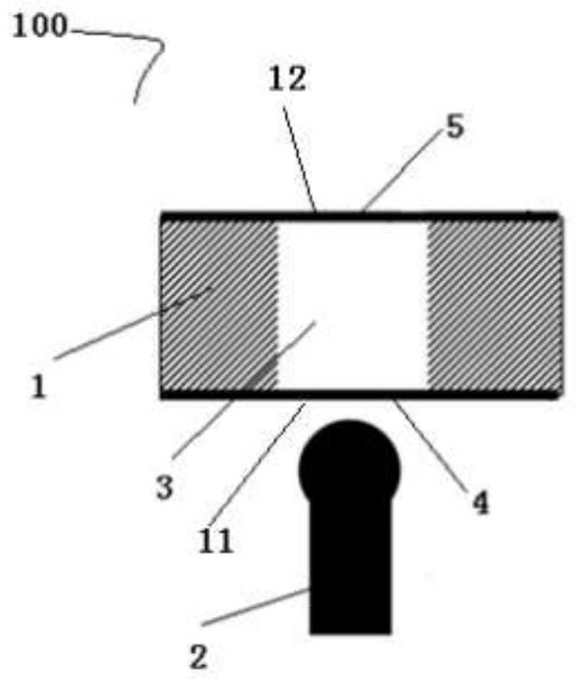
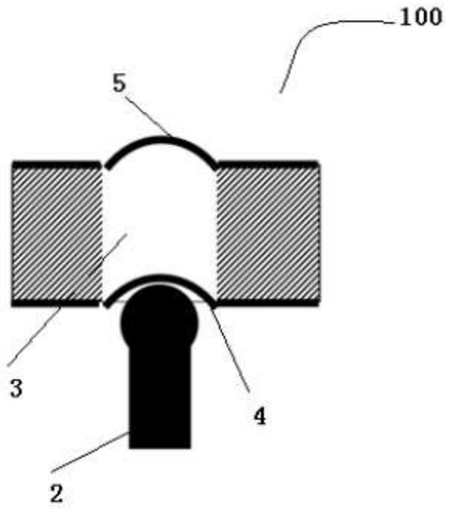
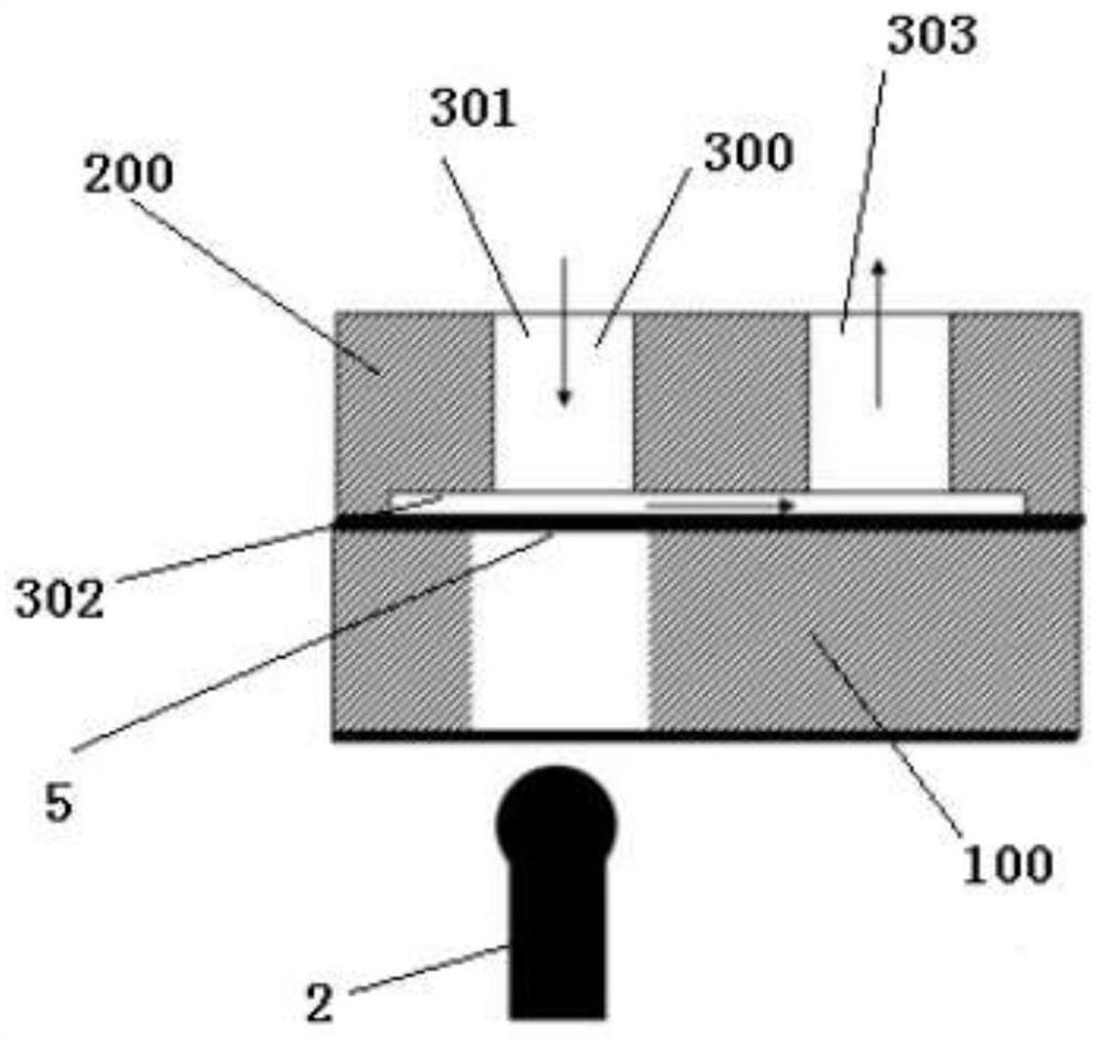
The embodiment of the invention provides a hydraulic switch valve for a micro-fluidic chip and the micro-fluidic chip. The hydraulic switch valve comprises a plate body and an ejector rod, the plate body is provided with at least one hollow part used for containing liquid, and the hollow part penetrates through the plate body and is provided with a first opening end and a second opening end; and a first thin film is arranged at the first opening end, a second thin film is arranged at the second opening end, the first thin film and the second thin film are used for sealing the hollow part, and the ejector rod applies pressure to the first thin film to enable the second thin film to deform so as to block a preset position of a micro-channel in the micro-fluidic chip. Compared with an existing air pressure valve, the hydraulic switch valve formed through the liquid force conduction property can directly control on-off of the micro-channel in the micro-fluidic chip, meanwhile, the requirement for leakproofness between the valve body and the chip is reduced, and on-off control over multiple micro-channels or multiple positions in one micro-channel is facilitated.

Description

technical field [0001] The disclosure relates to the field of biological instruments, in particular to a hydraulic switching valve for a microfluidic chip and a microfluidic chip. Background technique [0002] In recent years, the rise and integration of various new technologies and methods have promoted the development, application and replacement of in vitro diagnostic (IVD) instruments and reagents. Microfluidic chips can integrate a series of basic operating units involved in the fields of chemistry and biology, such as sample preparation, reaction, separation, and detection, into a micron-sized chip. At the same time, the network formed based on microchannels can run through the entire system. , has the advantages of portability, low energy consumption, easy production, easy to master, etc., and is easy to meet the needs of life sciences for low-dose, more efficient, high-sensitivity, and rapid separation and analysis of biological samples. However, in the current use ...

Claims


Application Information

Patent Timeline
Patent Type & Authority Applications(China)
IPC IPC(8): F16K99/00B01L3/00
CPCF16K99/0015F16K99/0034B01L3/502738B01L2200/027B01L2200/10F16K2099/0084
Inventor 王琛瑜赵静张玙璠
Owner BOE TECH GRP CO LTD
Why Eureka
Try Eureka