
Quartz tuning fork gyroscope switch demodulation circuit

A technology of quartz tuning fork and demodulation circuit, applied in gyroscope/steering sensing equipment, gyro effect for speed measurement, instruments, etc., can solve the problems of extra error, extra error, change of angular velocity signal, etc., so as to avoid the demodulation error change. Effect

Active Publication Date: 2021-04-23
BEIJING AUTOMATION CONTROL EQUIP INST
View PDF10 Cites 0 Cited by
  • Summary
  • Abstract
  • Description
  • Claims
  • Application Information

AI Technical Summary

Problems solved by technology

[0005] The invention provides a switch demodulation circuit for a quartz tuning fork gyroscope, which can solve the technical problem that the angular velocity signal output by the switch demodulation circuit for a quartz tuning fork gyroscope in the prior art has an additional error and the additional error changes with the ambient temperature

Method used


Image

  • Quartz tuning fork gyroscope switch demodulation circuit
  • Quartz tuning fork gyroscope switch demodulation circuit
  • Quartz tuning fork gyroscope switch demodulation circuit

Examples


Embodiment Construction

[0020] It should be noted that, in the case of no conflict, the embodiments in the present application and the features in the embodiments can be combined with each other. The following will clearly and completely describe the technical solutions in the embodiments of the present invention with reference to the accompanying drawings in the embodiments of the present invention. Obviously, the described embodiments are only some, not all, embodiments of the present invention. The following description of at least one exemplary embodiment is merely illustrative in nature and in no way taken as limiting the invention, its application or uses. Based on the embodiments of the present invention, all other embodiments obtained by persons of ordinary skill in the art without creative efforts fall within the protection scope of the present invention.

[0021] It should be noted that the terminology used here is only for describing specific implementations, and is not intended to limit t...


PUM


Abstract

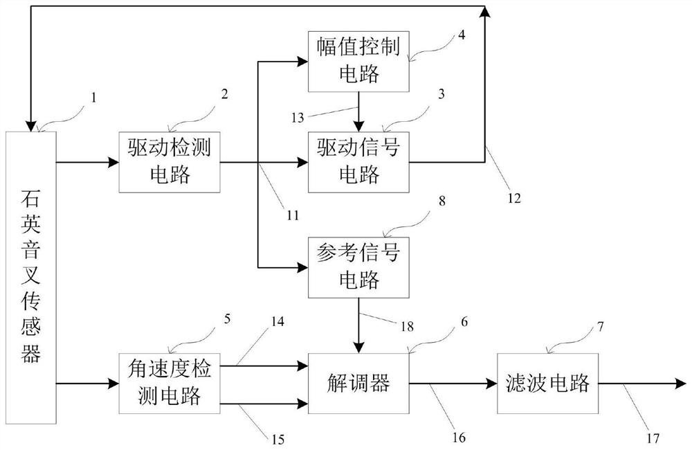
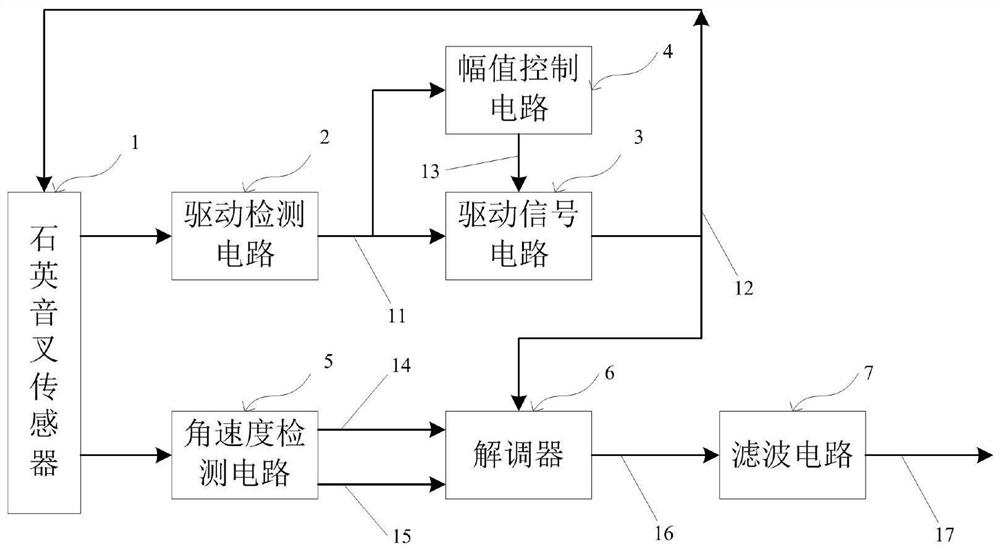
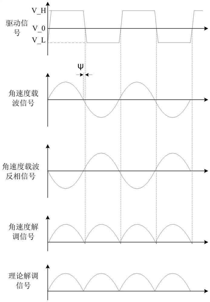
The invention provides a quartz tuning fork gyroscope switch demodulation circuit. The circuit comprises a quartz tuning fork sensor; a driving detection circuit which is connected with the quartz tuning fork sensor and is used for outputting a driving detection signal according to the charge signal; an amplitude control circuit; a driving signal circuit; a reference signal circuit which is connected with the driving detection circuit and is used for generating a demodulation reference signal according to the driving detection signal; an angular velocity detection circuit; a demodulator which is respectively connected with the angular velocity detection circuit and the reference signal circuit and is used for generating an angular velocity demodulation signal according to the demodulation reference signal, an angular velocity carrier signal and an angular velocity carrier inversion signal; and a filter circuit. According to the technical scheme, the technical problems that in the prior art, an angular velocity signal output by a quartz tuning fork gyroscope switch demodulation circuit has an additional error, and the additional error changes along with the environment temperature can be solved.

Description

technical field [0001] The invention relates to the technical field of a quartz tuning fork gyroscope measurement and control circuit, in particular to a quartz tuning fork gyroscope switch demodulation circuit. Background technique [0002] At present, the angular velocity demodulation in the measurement and control circuit of the quartz tuning fork gyroscope mostly adopts the method of switch demodulation. This method uses the method of multiplying the drive signal with the same frequency as the angular velocity carrier information and the angular velocity carrier to obtain the angular velocity signal, also known as in-phase demodulation. [0003] The quartz tuning fork gyroscope switch demodulation circuit in the prior art is such as figure 2 as shown, figure 2 The middle driving detection signal 11 is divided into two paths, one path is sent to the amplitude control circuit 4 to generate the amplitude control signal 13 for controlling the magnitude of the driving signal...

Claims


Application Information

Patent Timeline
Patent Type & Authority Applications(China)
IPC IPC(8): G01C19/5621
CPCG01C19/5621
Inventor 申燕超童栎杨星辉王汝弢
Owner BEIJING AUTOMATION CONTROL EQUIP INST
Learn More