
Crankshaft automatic indexing hydraulic clamp

A hydraulic fixture and automatic indexing technology, which is applied in clamping, clamping devices, manufacturing tools, etc., can solve the problems of large eccentricity error, low crankshaft machining efficiency, and poor crankshaft machining accuracy, so as to improve machining accuracy and improve Processing efficiency, clamping and stable effect

Active Publication Date: 2016-04-06
德州德隆(集团)机床有限责任公司
View PDF8 Cites 0 Cited by
  • Summary
  • Abstract
  • Description
  • Claims
  • Application Information

AI Technical Summary

Problems solved by technology

[0003] In order to solve the shortcomings and deficiencies in the prior art of low crankshaft machining efficiency, large orientation angle and eccentricity error of connecting rod diameter machining, and poor crankshaft machining accuracy, the present invention provides a crankshaft automatic indexing hydraulic fixture

Method used


Image

  • Crankshaft automatic indexing hydraulic clamp
  • Crankshaft automatic indexing hydraulic clamp
  • Crankshaft automatic indexing hydraulic clamp

Examples


Embodiment Construction

[0020] Combine below Figure 1-5 The present invention is described in detail to clarify the structural features and usage methods of the present invention.

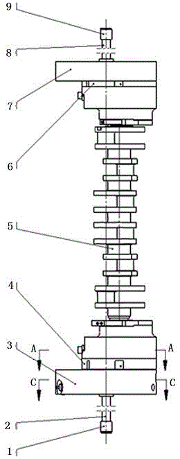
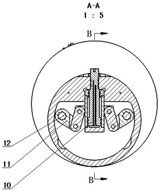
[0021] A crankshaft automatic indexing hydraulic clamp, the crankshaft 5 is installed between the front and rear clamps, the cylinder 10 is clamped after radial positioning by the main shaft, and the clamping claw 19 is connected with the hinge arm 11 and the transmission shaft 12, and the clamping claw is driven 19 crankshafts are clamped, and the above parts are all installed on the front main shaft 4.

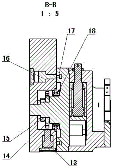
[0022] The front main shaft 4 is installed on the front clamp body 3 through the bearing 18, and can rotate on the front clamp body 3. The rear end of the front main shaft 4 is equipped with a precision indexing chainring 14 and a ratchet wheel 15, and the indexing oil cylinder 22 stirs the front main shaft 4 and the crankshaft 5 to rotate together through the swing arm 23. The stroke of the index cylinder 22 is adju...


PUM


Abstract

In China, crankshaft processing is still in a relative laggard state, crankshaft processing efficiency is low, a direction and position angle and an eccentric distance for connecting rod radial processing are great, and crankshaft processing precision is poor. According to a crankshaft automatic indexing hydraulic clamp, a front clamp body assembly comprises a front main shaft used for mounting a crankshaft, a front clamp body which is mounted on the front main shaft by virtue of a bearing, and rotates on the front main shaft, as well as a rotary oil pressure joint and a front oil giving rod capable of conveying hydraulic oil to the front clamp body; and the front clamp body assembly and a rear clamp body assembly are the same in structure. According to the scheme adopted by the invention, the crankshaft automatic indexing hydraulic clamp has the beneficial effects that: the hydraulic clamp adopts hydraulic drive for clamping, indexing and positioning, and locking of the crankshaft, programmable control can be carried out on the hydraulic system by virtue of a numerical-control system, full-automatic control is realized, processing precision is improved, and processing efficiency is improved.

Description

technical field [0001] The patent of the present invention relates to an automatic clamp for a lathe or a grinder, specifically a crankshaft automatic indexing hydraulic clamp. Background technique [0002] At present, with the rapid development of my country's shipbuilding and automobile industries, the demand for engine crankshafts by engine manufacturers is increasing rapidly. However, my country is still relatively backward in the processing of crankshafts, especially the processing technology of crankshaft connecting rod diameters of automobiles, heavy trucks, and small diesel engines. For example, heavy-duty crankshafts are mainly made of three sets of manual fixtures, each of which corresponds to 1-6, 2-5, and 3-4 corners, and are processed separately on three machine tools. After three clamping and positioning of the fixtures Only conversion can complete the clamping and processing, which leads to low processing efficiency of the crankshaft, a large increase in the ...

Claims


Application Information

Patent Timeline
IPC IPC(8): B23Q3/12
CPCB23Q3/12B23Q2703/105
Inventor 朱铁强鲁娜赵吉明李乐李书月
Owner 德州德隆(集团)机床有限责任公司
Learn More