Projector virtual touch tracking method, device and system based on visible light

A technology of virtual touch and visible light, which is applied in the field of projection display, can solve problems such as ineffective operation, and achieve the effects of high portability, good stability and flexibility, and low price

Pending Publication Date: 2021-04-23
CHENGDU XGIMI TECH CO LTD
8 Cites 2 Cited by

AI-Extracted Technical Summary

Problems solved by technology

Since infrared light cannot be seen by human eyes, when the infrared touch peripheral device touches the corresponding area, if the infrared touch peripheral device does not emit infrared light, the system will judge that no touch has occurred, and the user does not know the...

Method used

Light spot detection: the light-emitting light spot of the touch peripheral can be designed, usually a circular light-emitting light spot is selected, so the light spot extraction is mainly to detect the light spot that meets certain geometric constraints and conditions in the binary image of each channel, for example Specifically, this application extracts four constraints to perform spot detection in the binary image. First, the Canny edge search is performed on the binary image, and then the opencv's findContours() function is used to find the contour and obtain the contour set, which is convenient for subsequent contour calculations:
Usually contain some noises in the image that camera shoots, and actual noise mostly is white noise, therefore by carrying out Gaussian filtering to original image, reaches the purpose of removing image noise, Gaussian filtering window can be chosen according to image resolution, as The filter window size is selected as 3*3. Then channel separation is performed on the filtered image, that is, the R, G, and B three-color channel images are respectively taken out.
Wherein, thresdk represents the k channel threshold, and ik is exactly the grayscale value of the corresponding channel of spot color, so just can process and generate binary image by simple fixed thre...

Abstract

The invention discloses a projector virtual touch tracking method, device and system based on visible light, and relates to the technical field of projection display. The method comprises the following steps: acquiring an image acquired by a camera, wherein the image comprises a projection picture and a visible light spot emitted by a touch peripheral; generating a touch signal according to an image; and realizing virtual touch and/or tracking according to the touch signal. According to the invention, virtual touch of the projector is realized based on a method of combining a portable touch peripheral and a specific color extraction algorithm, the price is low, the portability is high, and the stability and the flexibility are relatively good; a user can visually know whether the touch peripheral emits effective light or not, invalid operation can be effectively avoided, and user experience is improved; by means of the method, multiple touch peripherals can be triggered at the same time, and a trajectory tracking function is achieved.

Application Domain

Picture reproducers using projection devicesInput/output processes for data processing

Technology Topic

EngineeringComputer graphics (images) +6

Image

  • Projector virtual touch tracking method, device and system based on visible light
  • Projector virtual touch tracking method, device and system based on visible light
  • Projector virtual touch tracking method, device and system based on visible light

Examples

  • Experimental program(1)

Example Embodiment

[0056]In order to better understand the technical solutions in the present application, the technical solutions in the present application embodiment will be described in conjunction with the drawings in the present application embodiments, and will be described in conjunction with the drawings in the present application. The embodiment is merely the embodiment of the present application, not all of the embodiments. It will be appreciated that the specific embodiments described herein are intended to explain the present application and is not intended to limit the present application. Based on the embodiments in the present application, one of ordinary skill in the art does not have all other embodiments obtained without creative labor, and should belong to the scope of the present application. Further, although the disclosure of this application will be described in terms of an exemplary one or from example, it is understood that various aspects of the disclosure may also form a complete technical solution. In the case of an unable conflict, the features of the following embodiments and embodiments can be combined with each other.
[0057]In the present application embodiment, "Examples", ",", ",,,,,,,,,,,,,,,,,,,,,,,,,,,,,,,,,,,,,,,,,,,,,,,,,,,,,,,, Any embodiment or design scheme described as "Example" in this application should not be construed as being more preferred or more advantageous than other embodiments or design. Specifically, the word use of the example is intended to present a concept in a specific manner.
[0058]Unless otherwise defined, the technical term or scientific terminology used in this application should be the usual meaning of people who have general skills in the art of the present application. The "first", "second" and similar words used in this application do not represent any order, quantity, or importance, but only for distinguishment, and the meaning of the corresponding terms can be the same or different. Similar words to "include" or "include", meaning that the elements or objects of the previously mentioned previously enumerated elements or objects that appear later in the word, without excluding other elements or objects.
[0059]The technical solutions in the present application will be described below in conjunction with the drawings.
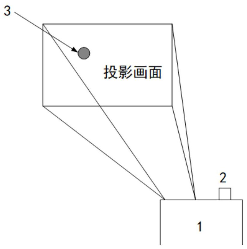
[0060]figure 1 A structural diagram of a visible projector virtual touch tracking system based on the present application embodiment. Such asfigure 1 As shown, the system includes projector 1, camera 2 and touch peripheral 3, and touch peripheral 3 can have portable, trace power consumption, infigure 1 In the illustrated embodiment, the camera 2 is a camera mounted within the projector 1, reducing costs. Projector 1 Projection screen, user opens the touch peripheral 3, the hand-held peripheral 3 enters the picture area, touch the area of ​​the touch, the touch peripheral 3 issues visible spot; camera 2 collects images in real time; That is, the touch signal can be generated according to the image, and virtual touch and / or tracking is achieved based on the touch signal. Use the touch peripheral 3 to send a visible spot, the user can intuitively know whether the touch peripheter is effective light to effectively avoid invalid operations and improve the user experience.
[0061]In some embodiments, a touch peripheral with emission discoloration visible spot can also be used, and the touch peripheral has a function of switching the light source color of the transmitted light when the touch is characterized, i.e., touch and no touch occurs. At the time of control, the visible spot of different colors,,,,,,,,,,,,,,,,,,,,,,,,,,,,,,,,,,,,,,,,,,,,,,,,,,,,,,,, The touch peripheral can include a battery module, a touch module, and a light-emitting module, which is used to provide a power supply for each component of the touch peripheral; the touch module is used for touch; the light emitting module is used to touch at the touch The external setting is in the power-on state. When the touch module does not touch, the first visible light spot is issued. When the touch module is in touch, the second visible spot is emitted, wherein the first visible light is in the second visible light. Color is different. The touch peripheral is preferably a touch peripheral of a pen, the touch module is set in the nib, and the light-emitting module is set to the pen end, the pen is passed, and the pen end becomes the second visible spot spot, when there is no touch, the pen end is changed to The first visible light spot. Touch peripherals When there is no touch and touch, the visible spot of different colors can be made more stable to use multi-channel uniqueness to remove the influence of the projector's active light source, while variable visible light can be more convenient for users. Get the current touch state.
[0062]In the following examples, when the touch peripheral does not have a touch, a blue spot is emitted, and the red spot is emitted as an example to perform the visible light-based projector virtual touch tracking method. Further illustrative, the color of the first visible light and the second visible light of the present application include, but is not limited to, red and blue, as long as there is color change and the camera can capture the color difference, such as blue white, yellow blue, etc.
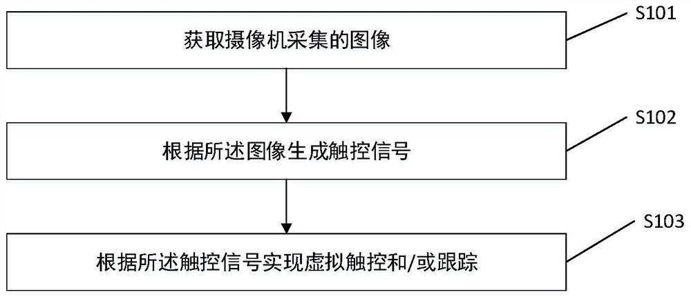
[0063]figure 2 A flow chart of a visible projector virtual touch tracking method based on the embodiment of the present application embodiment. Such asfigure 2 As shown, the virtual touch method based on visible light-based projector includes the following steps:
[0064]S101. Access the image captured by the camera, the image contains the visible photographic spot emitted by the projection screen and the touch peripheral.
[0065]The camera can be a camera that is independent of the projector, or a camera mounted in the projector.
[0066]S102. A touch signal is generated according to the image.
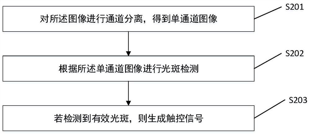
[0067]The images collected by the camera have R, G, B three-channel, where R represents red, g represents green, b represents a blue channel. Such asimage 3 As shown, step S102 specifically includes the following steps:
[0068]S201. Separation of the image to obtain a single channel image.
[0069]The present application example is illustrated by the RGB format image, i.e., after the channel is separated, the R, G, and B single channel images are obtained. The present application includes, but is not limited to, RGB, HSV, YUV and other format images, all channel separation methods can be used to achieve single channel image extraction, and subsequent spot detection under separate single-channel images.
[0070]In the image captured by the camera, there is some noise, and the actual noise is mostly white noise, so by performing Gauss filtering of the original image, the purpose of removing image noise, the Gaussian filter window can be selected according to image resolution, such as filtering window size Selected to 3 * 3. Then, the filtered image is separated, ie, the R, G, and B three-color channel image is taken out, respectively.
[0071]S202. Scrap detection is performed according to the single channel image.
[0072]The single-channel image is obtained by step S201, and the single-channel image is threw a threshold, and a binary image is generated, and the spot detection is performed in a binary image. Since the different spot color corresponds to a different color channel, such as the blue spot corresponding to the B channel, the red spot corresponds to the RGB three-way channel, the yellow corresponding RB two channels, etc., the corresponding single channel image can be selected according to the color of the spot. The spot detection was performed to reduce the amount of calculation, and the spot color according to the present application is red and blue, and the two single channel images are selected to detect the spot. In other embodiments, if the spot color involves blue and white, select R, G, B three single-channel images to detect spot; if the color of the spot involves blue and yellow, select R, B two single channel images Scrapped. Therefore, when the RGB format image is selected, the spot color can be selected in red, green, and blue color, thereby reducing the amount of calculation.
[0073]Threshold: Because the spot color can be pre-design and control, its gradation value in each channel is within a range. If the grayscale value is expressed in the formula:
[0074]I = (i1, I2, I3)
[0075]Where i represents a spot color grayscale value, i1, I2, I3The gradation value corresponding to the three-channel, here is the order of RGB color channels, for pure blue visible light I = (i1= 0, I2= 0, I3= 255) For pure red visible light I = (i1= 255, i2= 0, I3= 0).
[0076]Therefore, in the RGB image, the channel threshold can be set, which is set to 0.7 times the channel gradation value, ie
[0077]THRESDk= 0.7 * ikK = 1, 2, 3
[0078]Among them, THRESDkRepresents K channel threshold, ikIt is the gray value of the spot color corresponding to the channel, so that each channel can be processed to generate a binary image by simple fixed threshold value, using a fixed threshold binarized method not only quickly improves the processing speed, and algorithm It will also be more stable, fixed threshold binarization relationship is:
[0079]
[0080]The thresd is the threshold, IrealThe gradation value of the single channel image is separated by the channel to the corresponding channel actual gray value, that is, the gradation value of the single channel image is separated.
[0081]Spot detection: The luminous light spot can be designed, typically a circular luminous spot, and thus the spot extraction is mainly in the binary image of each channel, and the spot is detected, and the spot, example, this The application extracts the four restrictions in the binary image to perform spot detection, first perform Canny edge lookups for the two-value image, then use the OpenCV's FindContors () function, find the contour, get the contour set, easy to make the back contour calculation:
[0082](1) Side area size: Obtain contour area, set the contour area up and down threshold (MINCONTOUREA, Max ContoursaRea), and the contour area is between the upper and lower thresholds is a valid profile;
[0083](2) The contour is approximative: elliptical fitting of the contour, if the elliptical fit is made by the least squares method, obtain the long and short axis length value of the ellipse, calculate the length diameter ratio: ratio = length / weith, where Length indicates the long axis length, Weith Indicates a short axis length, sets the long diameter than the upper and lower threshold (MIN Ratio, Max Ratio), and the profile between the upper and lower thresholds is a valid profile, and the threshold range can be selected according to the actual situation, such as taken (0.7, 1.3) .
[0084](3) Centrophe is close to: Get the quality of the contour and shape, the centroid represents the contour grayscale value center, and can calculate the moment of the contour by the OpenCV's MOMENTS () function, and then according to the multi-direction moment to the calculation method, obtained Contour quality:
[0085]x = M00
[0086]Y = M01 / M00 where the M10, M00, M01 is the first-order contour moment of the Moments () function calculated, x, y is the contour core X, Y coordinate, and the shape is the center of the elliptical, remembered as (x1, y1), set eccentric distance Distance, if the centroid and shackles are less than the eccentric distance Distance, the eccentric distance can be selected according to the actual situation, such as being set to 3 pixels.
[0087](4) When the touch peripherals occur, the spot color is designed in advance, when the spot detection is performed, when the spot is detected in the channel image corresponding to the spot color, the spot is a valid spot. In the present application, different brotherapy spots are not coincident because only one color spot is only emitted at the same time, and therefore, if the area having a high degree of degrees of degrees of area is detected in the vicinity of the R and B channels, it is considered an invalid spot.
[0088]In the present application embodiment, the above four conditions must be satisfied, and the profile is considered to be the final needs of the effective profile, i.e., the spot screening.
[0089]S203. If effective spot is detected, a touch signal is generated.
[0090]In the present application, if the effective spot is detected at the R channel, the B channel has not detected a valid spot, the touch, the touch signal is generated, and the touch signal is generated. Converse, if the active spot, the R channel is detected at the B channel If effective spot is not detected, the touch signal is not generated at this time.
[0091]Touch detection: When the touch occurs, the B channel detects the effective spot, and the corresponding area of ​​the R channel does not detect the effective spot. When a touch occurs, the active spot of the B channel disappears, and the effective spot in the R passage corresponds to the region. At this point, the touch is determined. Conversely, it means to cancel the touch.
[0092]Since the camera coordinate system is different from the projector coordinate system, it is necessary to map the occurrence zone to the projector end through the conversion relationship between the camera coordinate system and the projector coordinator, and the function is triggered.
[0093]Camera projector relational coordinate conversion calculation: camera capture images, extract four vertex coordinates (A, B, C, D) in camera images, corresponding to four coordinate top points under projector images (A1, B1, C1 , D1), by four points pair, the corresponding single-shouldable matrix H:
[0094]
[0095]among them Image coordinates for projectors, Camera image coordinates.
[0096]By the single physical matrix H, the core coordinates of the spot detected in the camera image can be converted to the projector coordinate system, and the positioning of the projector area can be completed, that is, according to the coordinate value of the projector coordinate system. Generate a touch signal to realize the function trigger of the corresponding area.
[0097]S103. Virtual touch and / or tracking is implemented based on the touch signal.
[0098]The present application embodiment can realize a multi-touch peripheral simultaneously triggered, and there is a trajectory tracking function. From the start of the touch, the active spot is tracked, and the touch trajectory tracking and interactive effects, such as the effectively spot trajectory of the active spot is the touch trajectory.
[0099]The present application example also provides a projector virtual touch tracking device based on visible light, which is configured to implement visible projector virtual touch tracking method based on the above embodiment, and can be implemented by hardware. Corresponding software implementation. The hardware or software includes one or more modules corresponding to the above functions, for example, an image for acquiring a camera collected, the image containing a visible picture and a touching peripheral image acquisition module; for according to The image generates a touch signal generating module for touch signals; a touch tracking implementation module for virtual touch and / or tracking according to the touch signal.
[0100]The present application embodiment also provides a projector including a processor and a memory that stores at least one program code in which at least one program code is loaded and executed by the processor to achieve the above. EXAMPLES The virtual touch tracking method based on visible light-based projector is involved.
[0101]The present application embodiment also provides a vast touch tracking system based on visible light-based projector, characterized in that the system includes a touch peripheral and a projector, the touch peripheral to the above embodiment Set, the projector is a projector according to the above embodiment.
[0102]The present application embodiment also provides a storage medium that stores at least one program code in which at least one program code is loaded and executed by a processor to achieve the above-described embodiment-based projector virtual touch. Control tracking method.
[0103]It should be understood that in various embodiments of the present application, the size of the serial number of the above processes does not mean that the order of execution order, some or all steps can be executed in parallel or have been executed, and the execution order of each process should be in its function and The intrinsic logic is determined, and there is no limit to the implementation process of the present application embodiment.
[0104]One of ordinary skill in the art will appreciate that the modules and algorithm steps described herein described herein can be implemented in electron hardware, or computer software and electronic hardware. These functions are executed in hardware or software, depending on the specific application and design constraint conditions of the technical solution. Professional technicians can use different methods to implement the described functions for each particular application, but this implementation should not be considered exceeded the scope of this application.
[0105]Those skilled in the art will clearly understand that in order to describe convenient and concise, the specific operation of the apparatus and module described above can be referred to the corresponding process in the foregoing method embodiment, and details are not described herein again.
[0106]In several embodiments provided herein, it should be understood that the disclosed devices and methods can be implemented in other ways. For example, the device embodiment described above is merely schematic, for example, the division of the module is only one logical function division, and there may be additional division modifications, such as multiple modules or components, may be combined or Can be integrated into another system, or some features can be ignored, or not executed. For example, the flowcharts and block diagrams in the drawings are displayed in the system architecture, functionality, and operation of the device, method, and computer program product according to various embodiments of the present application. In this regard, each of the flowcharts or block diagrams can represent a portion of a module, block, or code, and a portion of the module, block or code contains one or more of the blocks for implementing a predetermined logic function. Executive instructions. It should also be noted that in some implementations of the replacement, the functions labeled in the box can occur in the order than those labeled in the drawings. For example, two consecutive blocks can actually be performed in parallel, and they can sometimes be performed in reverse order, which is determined according to the functions involved. Also note that each block in block diagram and / or flowchart, as well as a combination of boxes in block diagrams and / or flowcharts, can be implemented using dedicated hardware-based systems that perform predetermined functions or motions. Or can be implemented with a combination of dedicated hardware to computer instructions. Another point, the coupling or direct coupling or communication connections displayed or discussed may be an electrical, mechanical or other form.
[0107]The modules illustrated as the separation member may be or may not be physically separated, as the component displayed as a module may be or may not be a physical unit, i.e., may be located in one place, or can be distributed to a plurality of network elements. The object of the present embodiment can be implemented in accordance with the actual needs to select the part or all of the modules.
[0108]Further, each functional module in the various embodiments of the present application can be integrated into one processing unit, or each module is alone, or two or more modules can be integrated into one unit.
[0109]The function can be stored in a computer readable storage medium if implemented in the form of a software function module and is used as a separate product. Based on this understanding, the technical solution of the present application essentially ors the contributing to the prior art or the portion of the technical solution can be embodied in the form of software products, the computer software product stores in a storage medium, including Several instructions are used to enable a computer device (which can be a personal computer, server, network device, or terminal device, etc.) to perform all or some of the steps of the methods described in this application. The aforementioned storage medium includes: U disk, mobile hard disk, ROM, RAM) disk, or a medium such as a variety of media that can store program code.
[0110]The terms used in the present application examples are only for the purposes of describing particular embodiments, not intended to limit the application. "One", "one", "one", "one", "" ",", "" ",", "," and "" ", used in the present application embodiment and the appended claims, are also intended to include many forms unless the context clearly represents other meanings. It should also be understood that the terms "and / or" as used herein refer to any or from any or more of the associated listing items. In this article, "/", generally indicates a "or" relationship of the associated object before and after.
[0111]Depending on the context, if "if" "if" "if" can be interpreted as "if" here, "or" when ... "or" in response to determination "or" respond to detection ". Similarly, depending on the context, the phrase "if it is determined" or "If the conditions or events of the statement" can be interpreted as "when it is determined" or "responds to the determination" or "as the condition or event "Or" in response to the detection (conditions or events). "
[0112]As described above, only the specific embodiments of the present application, but the scope of the present application is not limited thereto, any technicress, those skilled in the art, can easily think of change or replacement within the technical scope of the present application, It should be covered within the scope of protection of this application. Therefore, the protection of the present application should be based on the scope of protection of the claims.

PUM

no PUM

Description & Claims & Application Information

We can also present the details of the Description, Claims and Application information to help users get a comprehensive understanding of the technical details of the patent, such as background art, summary of invention, brief description of drawings, description of embodiments, and other original content. On the other hand, users can also determine the specific scope of protection of the technology through the list of claims; as well as understand the changes in the life cycle of the technology with the presentation of the patent timeline. Login to view more.

Similar technology patents

Shank installation structure and cutters

InactiveUS6966730B1easy to worklow price
Owner:MIYANAGA KK

Classification and recommendation of technical efficacy words

  • low price
  • Improve portability

Solar Charger Energy Management and Monitoring System

InactiveUS20160254698A1quick and efficient chargeimprove portability
Owner:ADVANCE ENERGY SOLUTIONS
Why Eureka
Try Eureka