Membrane column using novel upper flange and pressing sleeve

A compression sleeve and flange technology, applied in membrane technology, semi-permeable membrane separation, chemical instruments and methods, etc., can solve the problems of installation difficulty, weight increase, membrane column performance deterioration, etc., to reduce the difficulty of installation and maintenance, reduce The effect of weight, improved longevity and reliability

Active Publication Date: 2021-04-27
烟台金正环保科技有限公司
View PDF5 Cites 0 Cited by
  • Summary
  • Abstract
  • Description
  • Claims
  • Application Information

AI Technical Summary

Problems solved by technology

The purpose of this patent is the same as that of the previous patent. They both solve the problem that when the membrane column is working, the central tie rod will be stretched under force, which will reduce the compression of the O-ring installed on the deflector plate, and the tie rod will change instantaneously when the pressure changes. However, the response speed of the deflector and the sealing ring to the deformation is much slower than that of steel, which leads to deformation or misalignment of the deflector and the O-ring, resulting in the performance degradation or even damage of the membrane column.
[0003] However, in actual production, the applicant found that the previous patent had a series of problems such as complex structure, increased weight, and difficulty in installation, and the membrane column of the above-mentioned patented structure, compared with the lower pressure membrane column, had a series of problems such as product operation failure, so this patent proposed A new structure to solve the above problems

Method used


Image

  • Membrane column using novel upper flange and pressing sleeve
  • Membrane column using novel upper flange and pressing sleeve
  • Membrane column using novel upper flange and pressing sleeve

Examples


Embodiment 1

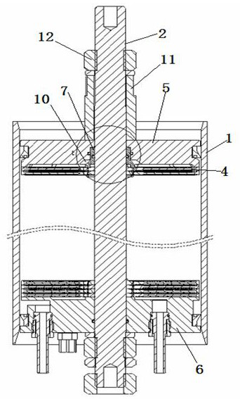
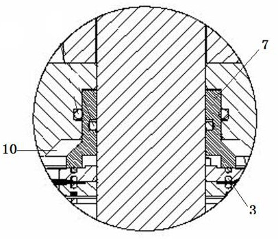
[0018] combine figure 1 , figure 2 As shown, a membrane column using a new type of upper flange and a compression sleeve includes a membrane housing 1, a central tie rod 2, a number of guide plates 4 with O-rings 3 installed on the center tie rod, and upper and lower ends of the center tie rod. The lower flange 5, 6, the upper section of the inner hole of the upper flange 5 is sealed with the center tie rod, and the lower section of the inner hole of the upper flange and the center tie rod reserve a space, and a compression sleeve 7 is installed in the space, and the bottom of the compression sleeve 7 The end presses the O-ring 3 of the guide plate, the top of the compression sleeve is in contact with the upper flange, and the compression sleeve 7 is sealed with the center tie rod 2 and the upper flange 5 through the sealing ring 8 . A gap 10 remains between the bottom outer wall of the compression sleeve 7 and the inner hole of the upper flange. The surface adjacent to the...

Embodiment 2

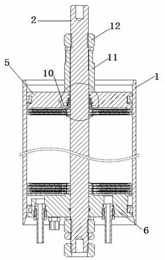
[0021] A membrane column using a new type of upper flange and a compression sleeve, including a membrane shell 1, a center tie rod 2, a number of guide plates 4 with O-rings 3 installed on the center tie rod, and upper and lower flanges at both ends of the center tie rod 5, 6, the upper section of the inner hole of the upper flange 5 is sealed with the center tie rod, the lower section of the inner hole of the upper flange 5 and the center tie rod 2 reserve a space 10, and the space 10 is equipped with a compression sleeve 7 and a disc spring 9, and the compression The bottom end of the cover presses the O-ring of the guide plate, the disc spring 9 is located between the top of the compression sleeve 7 and the upper flange 5, and the inner wall of the compression sleeve 7 is sealed with the central pull rod 2. A gap 10 remains between the bottom outer wall of the compression sleeve and the inner hole of the upper flange. The surface adjacent to the upper part of the compressio...


PUM


Abstract

The invention belongs to the field of water treatment, and particularly relates to a membrane column using a novel upper flange and a pressing sleeve, which comprises a membrane shell, a central pull rod, a plurality of flow guide discs with O-shaped rings, an upper flange and a lower flange which are arranged on the two ends of the central pull rod, and is characterized in that the upper section of an inner hole of the upper flange is sealed with the central pull rod, a space is reserved between the lower section of the inner hole of the upper flange and the center pull rod, the pressing sleeve and a disc spring are installed in the space, the bottom end of the pressing sleeve presses the O-shaped ring of the flow guide disc, the disc spring is arranged at the top end of the pressing sleeve, and the inner wall of the pressing sleeve and the center pull rod are sealed. According to the invention, the prior patent structure is improved, the installation is convenient, the overall weight is reduced, and the defects of instability, even failure and the like in the operation of the prior patent product are avoided.

Description

technical field [0001] The invention belongs to the field of water treatment equipment, in particular to a membrane column using a novel upper flange and a compression sleeve. Background technique [0002] The present invention is an improvement on the applicant's previous patent "A Membrane Assembly with a Pre-tightening Force Compensation Mechanism for an O-ring O-ring of a Baffle" with the patent number ZL 202020252316.0. The purpose of this patent is the same as that of the previous patent. They both solve the problem that when the membrane column is working, the central tie rod will be stretched under force, resulting in a reduction in the compression of the O-ring installed on the guide plate, and the pull rod will change instantaneously when the pressure changes. However, the response speed of the deflector and the sealing ring to the deformation is much slower than that of steel, which leads to deformation or misalignment of the deflector and the O-ring, resulting in...

Claims


Application Information

Patent Timeline
Patent Type & Authority Applications(China)
IPC IPC(8): B01D63/00
CPCB01D63/00Y02W10/10
Inventor 李越彪连永明刘德华张卓
Owner 烟台金正环保科技有限公司
Why Eureka
Try Eureka